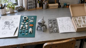
How are plastic model kits manufactured? A useful short answer is that the kit is built twice: first as a set of decisions, then as a set of physical parts.
On screen, a robot, vehicle or creature may already look finished. In the box, it still has to become labeled parts that a real person can find, hold and assemble. A shoulder shell needs room for the joint underneath it. A clear canopy must appear at the right step in the instructions. A small antenna needs a safe place in the pack-out.
That is why injection molding is only one part of plastic model kit development. The project moves through a manufacturing brief, product engineering, prototypes, tooling, tool trials, production approval, instructions and final pack-out.
Each review reveals something different. A digital model makes proportion easy to discuss. A printed prototype can expose an awkward build sequence. Tool-trial parts show what the production process actually creates. None of those reviews should be asked to prove everything at once.
Clear handoffs keep the current version, open issues and next decision visible. When production begins, the molded parts, instructions, packaging references and inspection plan should all describe the same kit. Buyers preparing a commercial project can also review FigCrafts’ custom plastic model kit manufacturing scope.
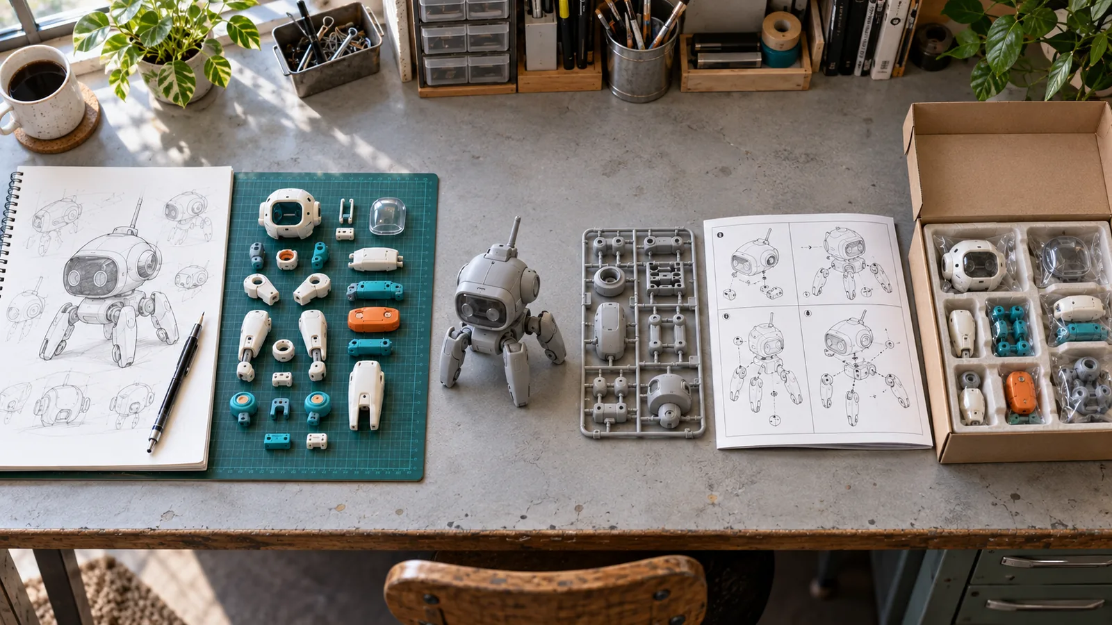
What to Settle Before Engineering Starts
A concept image can communicate the character, vehicle or object clearly while leaving most production decisions unanswered. Engineering still needs to know the intended scale, how the builder will assemble the kit, which accessories are included and what should be waiting inside the box.
A dramatic robot with folding wings and an oversized sword is fun to picture. Manufacturing asks the practical follow-up questions. Can the sword pass through the hand? Do the wings go on before the back shell closes? Will that long accessory fit the planned tray? Those answers begin to shape the product.
Start with the source material and its version. This may include concept art, turnarounds, drawings, a physical reference, a sculpt, 3D files or CAD data. Identify which file controls the current design.
Small contradictions matter. The front artwork may show a short backpack while the 3D file contains a longer one. A color key may show a clear visor that is opaque in the model. Engineering should not have to guess which reference wins.
The initial brief should also cover:
- finished scale and approximate dimensions;
- intended product use and expected builder experience;
- expected quantity and planned variants as project inputs;
- preferred assembly method, if already decided;
- known parts, accessories, decals and display elements;
- color separation and finish direction;
- instructions, packaging and pack-out scope;
- target market and applicable product requirements;
- desired schedule and any fixed approval dates;
- brand ownership, license or other authorization for the design.
Not every point needs a final answer on day one. It does need a status:
| Status | What it means | Simple example |
|---|---|---|
| Fixed | Ready to guide the next stage | Finished scale is approved |
| Provisional | A working direction that still needs confirmation | Glue assembly is preferred, pending build review |
| Open | No decision has been made | The visor may be clear or separately decorated |
A provisional scale should not quietly become the basis for finalized interfaces and packaging dimensions. An open visor decision should stay visible until the part and finish route is agreed.
The first useful handoff is therefore more than a folder of images. It is a clear project brief that identifies the current product, the references behind it and the decisions that still need review. Engineering can begin when the buyer and manufacturing team agree on that starting point.
Choose the Assembly and Product Route Early
Assembly changes the way a design becomes parts. Two kits can share the same silhouette and still need very different engineering because one snaps together and the other is glued.
Think about the builder for a moment. Can the hands reach the connector? Does a cover close before or after the inner frame goes in? Will a tiny detail be added early and remain exposed through the rest of the build? These are ordinary build questions, but they influence part separation and assembly order.
Material and color choices belong in the same conversation. A clear window, a rigid shell and a flexible detail do different jobs. A red stripe might become a separate colored part, a decorated area or a decal. Each route changes what must be engineered and approved.
| Early choice | What looks simple in the artwork | What may change in development |
|---|---|---|
| Snap-fit or glue assembly | Two parts meet along one seam | Connector design, access, build order and fit review |
| Clear or opaque canopy | The shape stays the same | Part separation, material direction and appearance approval |
| Molded color or decoration | One color boundary | Part layout, visible seams, artwork and sample scope |
| Shared or unique armor part | Two variants look similar | Geometry review, identifiers, instructions and version control |
Shared parts need proof, not optimism. Two shoulder shells may look identical from the front while hiding different connectors on the inside.
Instructions and packaging should begin alongside the product route. They depend on part numbers, assembly order, accessories and the physical arrangement of the kit. Leaving them until every molded part is finished makes mismatches harder to correct.
The complete route is easier to manage when every handoff has a clear purpose:
| Development stage | Buyer input | Reviewable output | Decision before moving on | If the product changes later |
|---|---|---|---|---|
| Manufacturing brief | Authorized references, scale, scope, quantity and open choices | Project assumptions and feasibility questions | Confirm what is fixed, provisional and unresolved | Update the brief before later work relies on it |
| Kit engineering | Approved direction and source files | Part architecture, interfaces, numbering and handoff files | Approve the geometry and sample route | Reopen affected engineering and sample work |
| Prototype review | Current files and agreed review points | Purpose-specific sample and issue record | Approve only what the sample can demonstrate | Keep unresolved properties open before tooling |
| Tooling release | Released geometry, part list and production direction | Tooling plan and release package | Authorize tooling work | Review whether the tool or trial plan must change |
| Tool trial | Tool-produced parts and agreed checks | Trial parts and a closed/open issue record | Correct, document an accepted deviation or release | Prevent open issues from becoming production assumptions |
| Production and pack-out | Released files, samples, instructions, packaging and inspection plan | Molded parts, complete kits and agreed release records | Approve finished-goods release under the project plan | Update every affected approved reference |
Some work may overlap according to the project. The table is not a fixed promise of timing or sample rounds. Its purpose is to keep each approval connected to the work it can reasonably release.
Turn the Design Into Parts That Can Be Made and Assembled
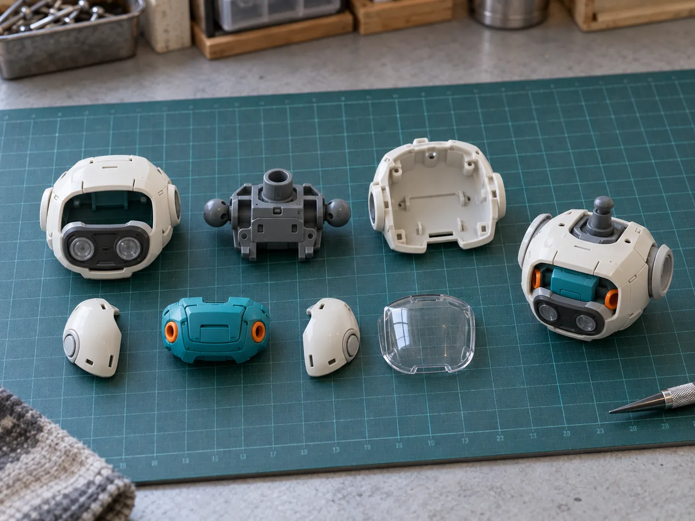
A beautiful surface is not yet a buildable kit. Product engineering gives it an internal logic: where the parts separate, how they meet and which piece the builder picks up next.
Take a robot chest as a simple example. In the artwork, it may look like one smooth shape with a colored center panel. In the kit, it could become an outer shell, a separate color insert and an inner connector. If the insert can only be fitted from behind, the shell cannot be closed too early. One visual detail has already affected three parts and the build sequence.
Part breakdown affects both appearance and production. A seam across a character’s face will be judged differently from one hidden under a backpack. Moving the seam can change the surrounding geometry, connection design or tooling approach. Color groups, clear areas and decorated details may also influence which features belong together.
Every connection also needs a job. Some parts only need to locate neatly. Some must stay together. Others must be removable or move after assembly. Once the job is clear, the review can focus on the real requirement instead of a generic fit rule.
Part numbers connect the engineering files to later work. The same identifiers should carry into sample reviews, issue lists, instructions and pack-out checks. If a shoulder cover is called one thing in the CAD record and something else in the instructions, a small naming difference can become a real production error.
Version control is just as practical. A handoff should identify the released files, the part list, known open points and the sample that comes next. FigCrafts’ 3D modeling and product engineering capability supports this transition from design intent to reviewable part architecture.
The engineering handoff is ready when the team can tell which parts belong to the kit, how they relate, what still needs proof and which file version should be used for the next sample.
What Can a Prototype Actually Confirm?
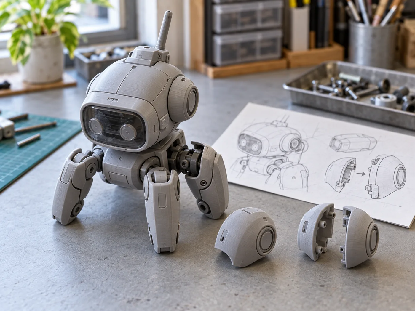
Before ordering a prototype, decide what you expect it to prove. Are you reviewing the silhouette, the planned part split, assembly access, color boundaries or another specific detail? The answer determines how the sample should be made and how it should be reviewed.
A printed sample can make form and assembly problems easier to see, but it does not behave exactly like a tool-produced part. Record the file version, what the team reviewed, what was accepted, what remains open and what happens next. The review should end with a clear decision on the selected points without turning the sample into blanket approval for the whole product.
| Question before review | The sample can help confirm | Still open |
|---|---|---|
| Do the proportions and visible forms look right? | Shape, scale, silhouette and major surface relationships | Production material, molded surface, tool-produced fit and repeatability |
| Can the parts be reached and assembled in the planned order? | Part access and assembly sequence when the sample follows the intended part layout | Final fit from tool-produced parts and effects created by the production process |
| Are the color breaks, decals and finish boundaries clear? | Appearance direction and placement references | Production repeatability and the final inspection standard |
Do not approve “the prototype” as one undivided package. Approve the version and the specific points that have been reviewed. A review note might say that the overall proportion is accepted while access to the shoulder joint is still open. The next team can then act on a clear decision instead of a vague instruction to continue.
Illustrative Buyer Scenario
This is an illustrative development scenario, not a FigCrafts client project.
An original mechanical model kit includes a broad shoulder shell. It looks balanced on screen. During a printed build review, however, the shell blocks the assembler’s access to the inner joint. The part split is revised before the files are released for tooling.
The sample has done a useful job: it exposed an assembly problem while the geometry could still be revised. Molded fit and surface finish remain open until tool-produced parts are available.
Illustrative change record — not FigCrafts project data
| Review point | Before the build review | After the revision |
|---|---|---|
| Planned shoulder-shell parts | 1 | 2 |
| Total planned molded parts | 18 | 19 |
| Main instruction steps | 6 | 7 |
The arithmetic is deliberately simple: one shell becomes two parts, so the planned molded-part count increases by one. The extra part also needs an identifier, a place in the assembly sequence and a line in the pack-out check. These figures are illustrative, not a recommended kit structure, quotation input or record from a FigCrafts project.
Choose the prototype and sample-making route according to what the team still needs to confirm.
What Must Be Approved Before Tooling Begins?
Tooling should begin from a released product definition, not from a folder that happens to contain the newest-looking file. The release package needs to identify the approved geometry and the production decisions that affect the tool.
Most teams have seen filenames such as final, final-v2 and final-approved. They are harmless until different people choose different files. A short release record removes the guesswork.
Confirm the part list, assembly intent and important interfaces. Record the material and color direction needed for tool planning. Visible surfaces, seam priorities, gate-sensitive areas and other appearance concerns should be clear enough for tooling review without turning the buyer document into a mold-design manual.
Open issues require special care. An accepted surface, a pending interface review and a known deviation do not carry the same status. List them separately. If the buyer accepts a condition, record what was accepted and on which version. If a point remains open, it should not disappear merely because tooling is ready to start.
The release record can be simple, but it should answer four questions:
- Which geometry and part list are being released?
- Which sample or review record supports the decision?
- Which deviations have been accepted?
- Which issues, if any, remain open and who owns the next action?
Written approval creates a common starting point for tooling and mold making. It also makes later change review much clearer. When geometry changes after tooling begins, the team can compare the request with the version released for tooling and determine what work must be reopened.
What to Check in Tool-Trial Parts
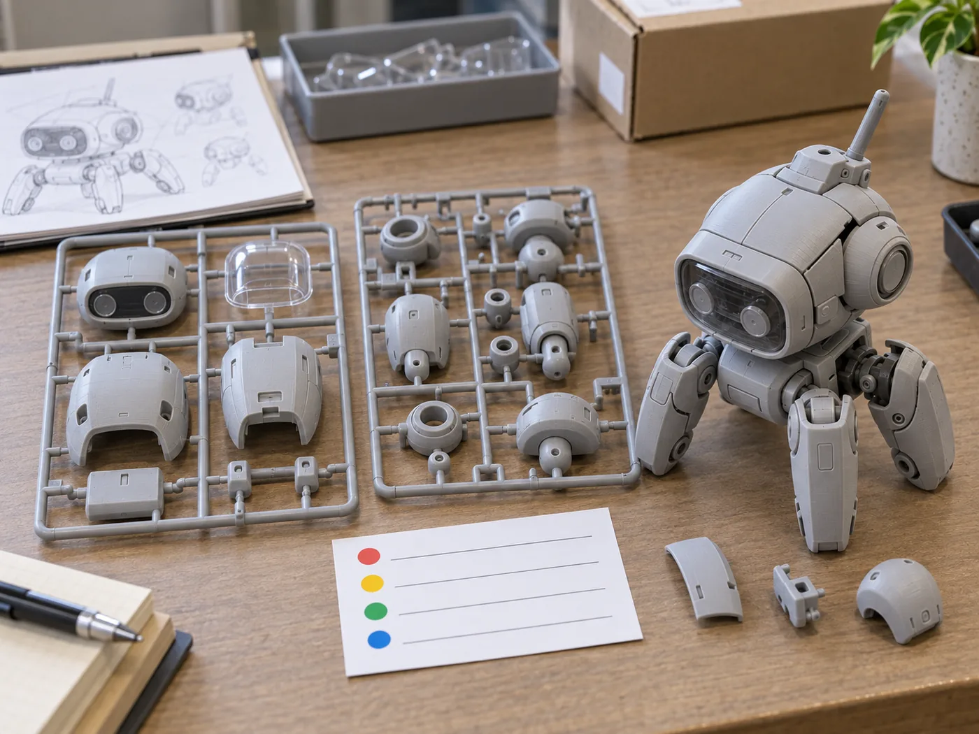
Tool-trial parts bring the review into the production process. Now the team can handle parts made through the intended molding route, fit them together and compare the result with the released product.
The observations are often very physical. A panel sits slightly proud. A connector is difficult to reach. Two similar caps are easy to mix up. A runner is incomplete. Each finding needs a decision, not just a red circle in a photograph.
Review the parts against the agreed plan. That may include selected dimensions or interfaces, fit and assembly, part identification, runner completeness and kit completeness where relevant. The exact inspection scope depends on the product and the risks identified before the trial; it should not be replaced by a universal checklist.
| Finding | Possible decision path | What it does not mean |
|---|---|---|
| A panel does not sit as approved | Correct the tool or process, or review the released geometry | Ignore the difference because the rest of the kit looks good |
| A visible difference is acceptable to the buyer | Record the accepted deviation for the identified version | Approve every other surface and part |
| Assembly access still fails | Revisit the approved product definition and affected tooling | Treat the issue as a photograph-only comment |
| The cause or result is unclear | Keep the point open and gather the agreed evidence | Release production by default |
Approving a correction is not the same as approving production. The correction still needs to be made and reviewed through the agreed route. Likewise, accepting one deviation does not approve unrelated surfaces, interfaces or parts.
The trial record should show the part and file revision, the issue, the agreed action, the owner and the status. Production can move forward when the required points are closed or formally accepted under the project plan.
Plan Instructions and Packaging Before the Kit Is Finished
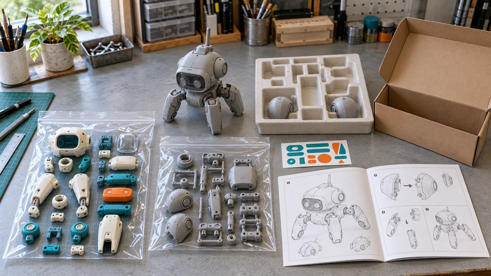
Instructions translate the approved assembly logic into the builder’s sequence. Their part numbers, orientation, callouts and accessory references need to match the physical kit. A diagram can look polished and still tell the builder to use the old shoulder shell, attach the right hand to the left arm or look for a decal that is no longer included.
Reconcile the instruction draft with the current part list and an actual assembly review. Check that left and right parts are distinguishable, optional steps are clear and decals or labels refer to the correct surfaces. When decoration or a packed accessory changes, update the corresponding references rather than treating the instruction file as a separate project.
Think of the part list, instructions and pack-out list as three copies of the same shopping list. If one still says “one shoulder shell” after the design changed to two, someone will eventually follow the wrong copy.
| Reference | What should agree |
|---|---|
| Part list | Every required molded part and accessory has the current identifier |
| Instructions | The identifiers, orientation and assembly order match the physical kit |
| Decal or label artwork | Each item points to the correct version and placement |
| Packaging reference | The box, insert or tray matches the approved product version |
| Pack-out list | The person packing the kit can confirm every included component |
Packaging develops in parallel. The kit may include bags, trays, blisters, inserts, boxes, labels or other components depending on the approved product plan. The pack-out list should identify the expected molded parts, accessories, printed items and packaging components for each version.
Packaging boxes, instructions, trays, blisters and other packaging materials are partner-produced. FigCrafts coordinates the project, confirms incoming components, performs assembly where included and completes final pack-out. That boundary should remain visible in the project scope and approval records.
A complete packaging approval covers more than graphics. The team also needs the correct version identifiers, packed arrangement and component list. Matching those references reduces the risk of placing the right molded kit with the wrong instructions, label or accessory set.
Keep Production Tied to the Approved Product
Production release brings several approved references together: the tool status, current files, accepted sample, part list, color and finish references, instructions, packaging and inspection plan. If one reference belongs to an older revision, the finished kit can drift away from the product the buyer approved.
For suitable projects, FigCrafts’ injection molding for model kits covers molded-part production after the relevant inputs have been released. First-off or first-article review, in-process checks and production records are set according to the agreed project and inspection plan. They are not identical for every kit.
Controls should follow the risks already identified. A kit with several similar parts may need careful identification and completeness checks. A product with a critical assembly sequence may require fit or build confirmation at agreed points. Multiple colorways or packaging versions need controls that prevent parts, printed items and labels from crossing between versions.
Imagine blue and red versions of the same mechanical kit moving through pack-out on the same project. The body geometry may be shared, but the decals, labels and box identifiers are not. One red decal sheet in a blue box is enough to make an otherwise complete kit wrong. Version control has to reach the packing table, not stop at the 3D file.
Final pack-out should reconcile the physical contents with the released bill of materials or pack-out list. The inspection and release decision can then refer to the same approved product used by engineering, tooling, instructions and packaging.
FigCrafts’ quality control and approval scope connects agreed requirements with inspection and release. Available records depend on the project and inspection plan. The important point is consistency: production should be checked against named, current references rather than memory or an unmarked sample.
Why Late Changes Reach Beyond the Design File
The same visual change can have a very different consequence depending on when it arrives. Moving a seam during early engineering may require a file update and another review. Requesting the same move after tooling starts may also affect the tool, trial parts, instructions and the approval plan.
| When the change arrives | References or work that may be affected | Decision before work continues |
|---|---|---|
| Before part engineering is released | Brief, scale, assembly route and part strategy | Update the working brief and confirm the new direction |
| After engineering or prototype approval | Geometry, part list, interfaces and sample record | Reopen the affected approval and release updated files |
| After tooling starts | Tooling, trial plan, geometry and commercial or schedule assumptions | Review feasibility and agree on the correction route |
| After production approval | Production references, instructions, packaging and inspection plan | Treat the request as a formal change across every affected reference |
Informal file replacement is risky because it hides the reach of the change. A revised shell may alter a connection. The connection may alter assembly. The new assembly may affect the instructions and packed arrangement. None of those effects is visible if the only record says “use the latest file.”
Record the request, the current approved version, the affected parts and the approvals that need to reopen. The team can then decide whether to accept the change, postpone it to another version or revise the active product through the agreed route.
Frequently Asked Questions About Plastic Model Kit Development
Do I Need Finished 3D Files to Start a Manufacturing Review?
No. Concept art, turnarounds, drawings, a physical reference or an early 3D model can support an initial discussion. Send the most complete material you currently have and identify its version.
The manufacturer still needs to know what is fixed and what remains open. Tooling cannot begin from an early concept alone. The design must first become reviewed part geometry, an approved part list and a released manufacturing handoff.
Can a 3D-Printed Prototype Approve Injection-Molded Production?
Not by itself. A printed prototype may be useful for checking shape, proportion, assembly access and selected interfaces when the sample method supports those questions.
It does not automatically confirm the production material, molded surface, tool-produced fit or repeatability. Keep those points open until the appropriate tool-produced parts and production references are reviewed.
What Should Be Approved Before Tooling Begins?
Approve the released geometry, part list, assembly intent, important interfaces and the material or color direction needed for tooling. Visible-surface priorities, known deviations and unresolved points should also be recorded.
The release should name the actual file version. A folder containing several files called “final” is not enough to tell the tooling team which product has been approved.
When Should Instructions and Packaging Work Begin?
Begin once the part numbering and assembly route are stable enough to create a working sequence. Do not wait until every molded part is finished. Instructions, labels, inserts and pack-out requirements often reveal mismatched identifiers or missing components while they can still be corrected.
Packaging boxes, instructions, trays, blisters and other packaging materials are partner-produced. FigCrafts coordinates the project, confirms incoming components, performs assembly where included and completes final pack-out.
Can Several Model-Kit Versions Share the Same Parts?
They can when the approved geometry, interfaces, material direction, surface requirements and relevant finishes are genuinely compatible. Similar appearance alone is not enough.
Treat a proposed shared part as an engineering question. Confirm which versions use it, how it will be identified and whether different colors, decals, instructions or packaging still require separate production control.
What to Send for a Production Review
A useful review starts with the current project, not a perfect final package. Send the information that already exists and mark what is still open:
- company or organization and the product’s ownership, license or other authorization status;
- concept art, references, physical sample, 3D or CAD files and the current version;
- intended finished scale and approximate dimensions;
- expected total quantity and planned variants;
- assembly method and intended builder experience;
- material direction, if known;
- color separation, finishes, decals and accessories;
- instruction and packaging scope;
- target market and applicable requirements;
- desired schedule and current approval status.
Share your concept art or 3D files, finished scale, expected quantity, assembly method, color and finish direction, packaging requirements, target market and schedule. FigCrafts can review the development route and identify the decisions needed before tooling.
We work with brand-owned, licensed or otherwise authorized designs. Proof of rights may be requested before production.