
FigCrafts develops authorized figure and model-kit inputs into part architecture, interfaces, assembly logic and geometry prepared for the agreed prototype or manufacturing handoff.
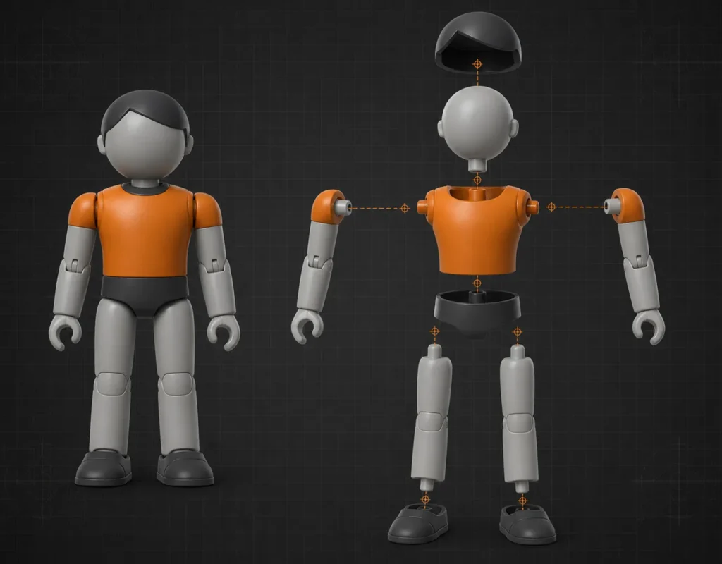
Start with the best available source
Different Inputs Create Different Engineering Work
FigCrafts can begin with early artwork, existing 3D/CAD or an authorized physical reference. The first review identifies what is defined, what conflicts and what still needs a buyer decision.
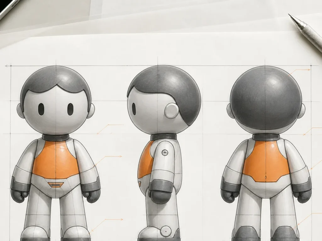
Artwork or Turnarounds
Define proportion, pose, scale, missing views, character details and the intended physical product before geometry is built.
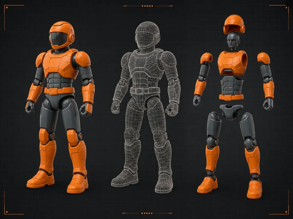
Existing 3D or CAD
Review geometry condition, scale, separate bodies, interfaces, visible surfaces and suitability for the next physical process.
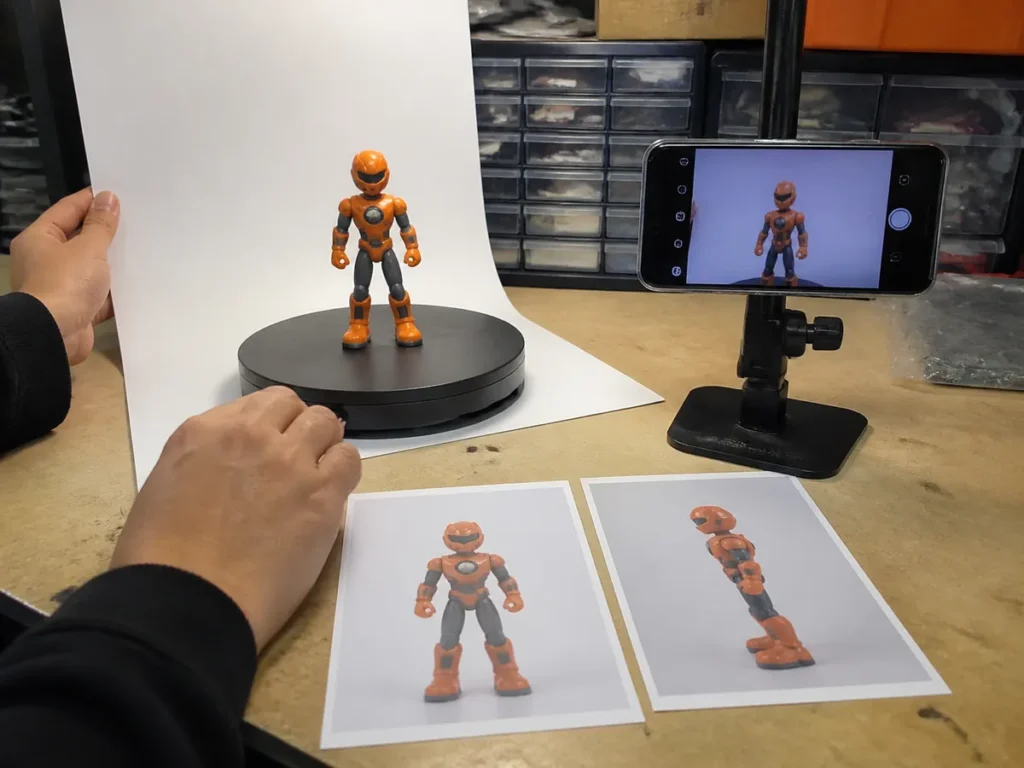
Authorized Physical Reference
Use authorized photos or samples to reconstruct form and relationships while separating measured facts from interpretation.
Product architecture before surface detail
The Model Must Explain How the Product Exists
A convincing shape is only one layer. The engineering model connects part boundaries, interfaces, forming direction, finish strategy, assembly sequence and the finished-product envelope.
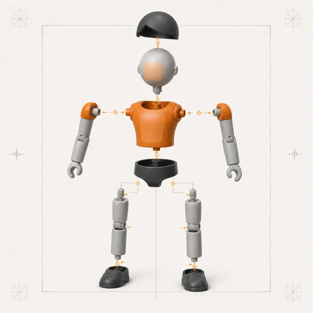
One character, different product systems
The Engineering Route Follows the Product
Model kits, articulated figures, painted display figures and hollow vinyl toys need different part, interface, appearance and validation strategies.
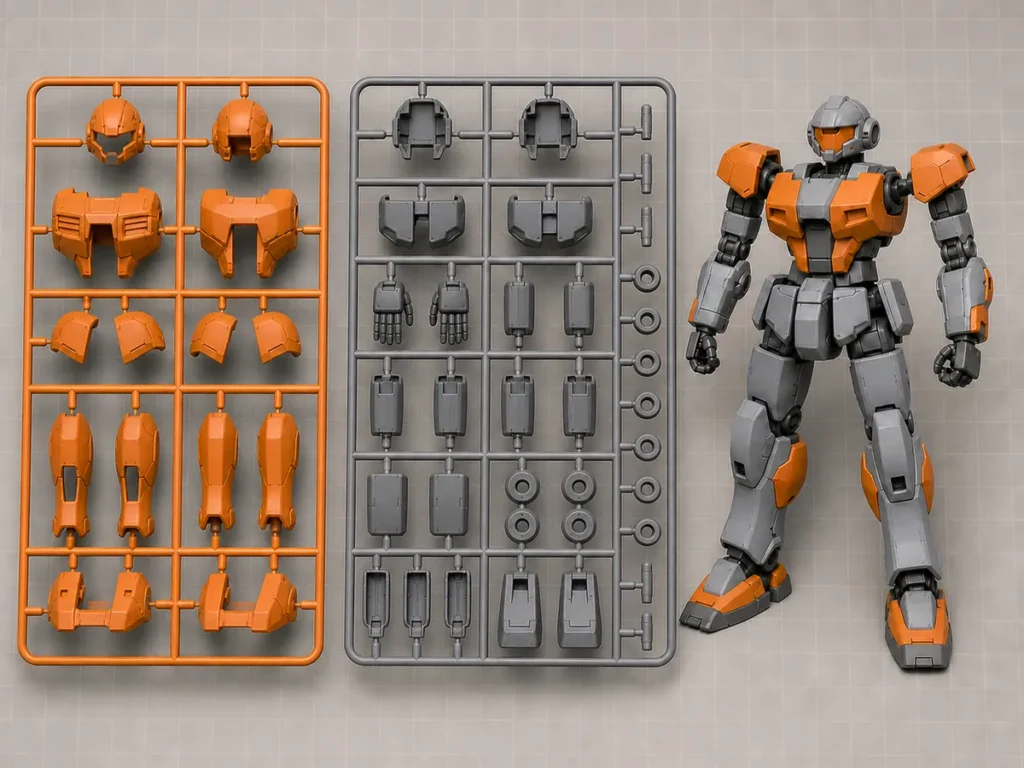
Plastic Model Kits
Part breakdown, runner grouping, gate-sensitive surfaces, fit logic, variants and instruction inputs.
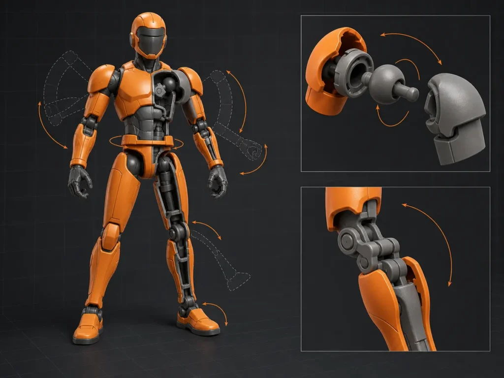
Action Figures
Joint placement, motion goals, material zones, alternate parts, accessories and assembly access.
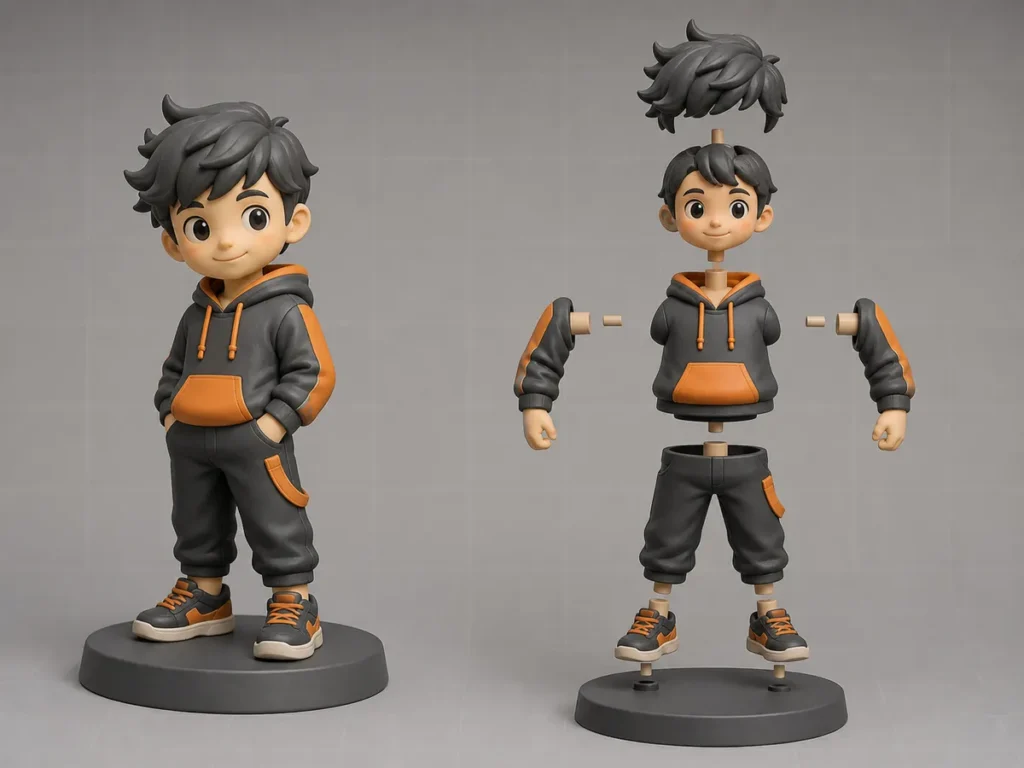
PVC Figures
Stability, multi-part construction, visible joins, color separation, decoration and display condition.
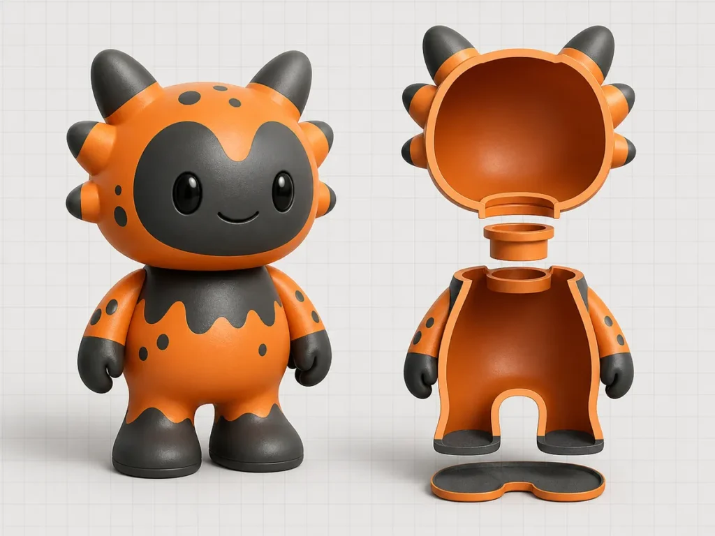
Vinyl Toys
Hollow form, openings, part release, seam or trim zones, balance, inserts and surface treatment.
Resolve coupled decisions early
Find the Conflict Before It Becomes Physical Rework
Engineering review makes critical assumptions visible before the project moves into prototype, DFM or production tooling.
Review part construction before priority surfaces are interrupted by avoidable seams.
Assign detail to molding, engraving, printing, painting or a separate component.
Identify interfaces that need physical validation under the selected material and process.
Balance movement, holding force, assembly access and protection from overstress.
Coordinate formed color, separate parts, paint, printing and manual detail.
Relate pose, projections and accessories to protection and retail presentation.
Connect digital and physical review
Use the Next Sample to Validate a Defined Decision
A rendering supports visual review. The next physical route should test the form, fit, assembly, handling or appearance question that remains open.
Review Prototype & Sample Making →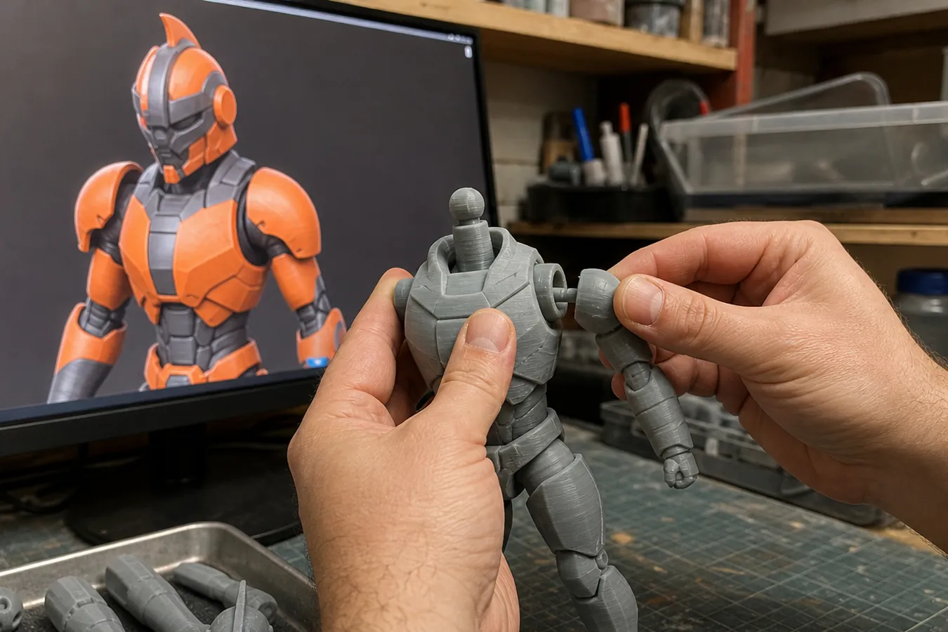
Approve the intended form, scale, part plan and interface intent.
Test form, fit, assembly, handling or appearance using a suitable route.
Release approved geometry and engineering notes for DFM or the agreed next stage.
Controlled engineering workflow
From Source Review to a Manufacturing Handoff
The sequence adapts to the product and starting data. Review stages and outputs are agreed before detailed work begins.
Confirm authorized inputs, product route, size, function, quantity, market and target next step.
Identify missing views, conflicting references, geometry condition and decisions needed to begin.
Establish silhouette, proportion, pose, finished dimensions and consistency across variants.
Define parts, interfaces, visible surfaces, process zones, assembly and pack-out relationships.
Consolidate feedback, revise the agreed scope and release the intended digital baseline.
Prepare the agreed package for prototype, DFM, tooling or another manufacturing stage.
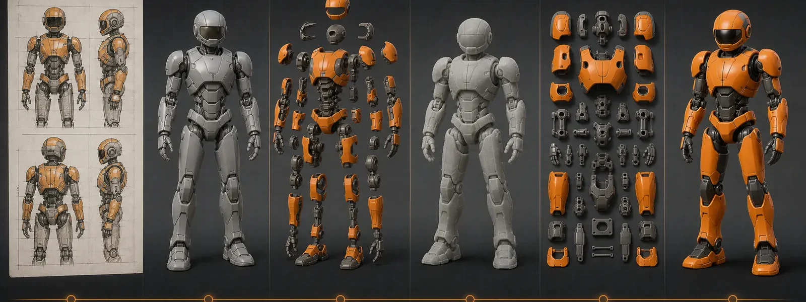
Possible engineering outputs
Define the Handoff by Its Intended Use
The agreed package may include the outputs below according to the starting data, product architecture and next manufacturing stage. File formats and native-file delivery are confirmed separately.
Form, Scale & Proportion Views
Views or review geometry used to approve silhouette, pose, main details and finished dimensions.
Exploded Part Breakdown
A part map or exploded view showing component boundaries, accessories, variants and assembly relationships.
Joint & Interface Details
Detail views showing locating, connection, movement or retention intent for identified interfaces.
Assembly Sequence & Fit Intent
Assembly order, access, orientation and the intended relationship between critical components.
Prototype Geometry
Geometry prepared for the selected sample route and the physical question that sample must answer.
DFM or Tooling Handoff
Approved geometry and engineering notes prepared for manufacturability review and the agreed next process.
Inputs for an effective engineering review
Send the Product Intent, Not Only a File
Share the best available authorized source plus the commercial and manufacturing context. Missing information can be identified during the first review.
Artwork, turnarounds, photos, physical reference or existing 3D/CAD, with the current revision identified.
Product type, finished size or scale, pose, function, accessories, variants and intended interaction.
Estimated quantity and SKUs, preferred materials if known, finish, assembly, packaging and target market.
What the model must support next: visual approval, prototype, DFM, tooling, revision or production handoff.
Identify the main contact for design, engineering and sample feedback so revisions can be consolidated.
Target schedule, known dependencies and whether an NDA is required before detailed file exchange.
3D modeling buyer FAQ
Practical Questions Before Modeling Starts
Exact formats, deliverables and validation routes are confirmed for the project.
Continue to the next physical stage
Connect the Model to Product, Sample and Tooling
Use the next page according to the immediate manufacturing question.
Compare the product systems and identify the intended finished object.
Physical ValidationChoose what the next physical sample must prove before tooling.
Production ToolingMove approved product architecture into DFM, tool design and trial.
Approval & ReleaseDefine the references, checks and release decisions for the product.
Prepare the next manufacturing step
Review the Source, Product Intent and Required Handoff
Share authorized artwork, photos, samples or 3D data together with product type, size, function, quantity, finish, packaging, target market and schedule.