Move an approved product design through product-specific DFM, mold design, machining, tool trials and agreed corrections before routine production begins.
What Should Be Defined Before Tooling Starts?
When key product decisions are still open, a prototype or focused engineering review should come before tooling.
Product Geometry & Parts
Approved 3D data or physical references should show the parts, interfaces and assembly direction.
Material & Production Plan
Material direction, quantity, color variants and decoration affect the tool set and cavity grouping.
Critical Fits & Surfaces
Joints, snaps, pins, sockets, assembly fits, character faces, polished panels and decorated zones need explicit priorities before tool design is released.
Approval and Commercial Boundaries
The parties should know who approves machining, trial corrections and production release, and which tooling terms will be recorded in the project agreement.
Tooling Priorities Change With the Product
Runner logic is not the same as joint logic, and a static figure does not create the same risks as a customer-assembled kit. The product route determines what the tool must protect.
Plastic Model Kits
Part and color grouping, runners, gate positions, visible nub areas, fit and build sequence.
Action Figures
Joints, movement, clearance, retention, mixed materials, finish protection and assembly access.
PVC & Collectible Figures
Part split, mold release, visible seams, stability, paint boundaries and joining methods.
Product-Specific DFM Before Machining
A decision that helps filling can move evidence onto a visible surface. A split that helps release can create a seam across a decorated face. DFM evaluates these interactions before machining.
Geometry and Release
Review draft, undercuts, shutoffs, walls and release direction.
Parting and Appearance
Protect character faces, polished panels and other important visible surfaces.
Runner, Gate and Fill
Evaluate material flow, gate evidence, part balance and runner organization.
Venting, Cooling and Ejection
Plan reliable filling, temperature control and part removal.
Dimensions and Assembly
Identify the interfaces and project-defined dimensions that affect fit and function.
Tool, Press and Production Match
Check the intended material, press route and production sequence together.
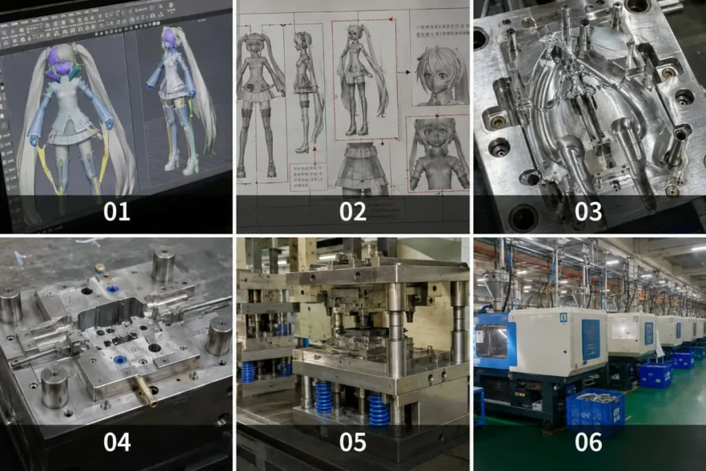
From DFM to Production-Ready Tooling
Every stage converts an open question into an approved baseline, reviewable physical evidence or a controlled release decision.
Tooling Review
Confirm parts, interfaces, visible surfaces, materials, quantity, variants and required checks.
Mold Design
Develop the product-specific split, cavity grouping, runner, gate, ejection and cooling approach.
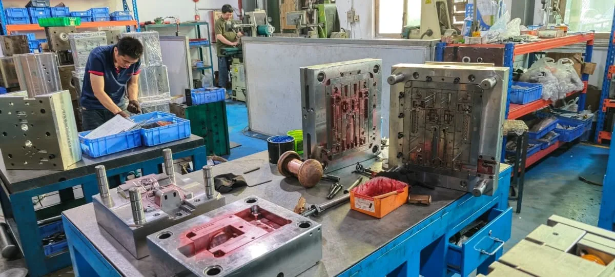
Machining and Tool Assembly
Build the approved tool and record agreed technical changes.
Controlled Tool Trial
Produce trial parts and review forming, surfaces, dimensions, fit and assembly.
Correction and Verification
Separate tool corrections from buyer-requested design changes, then verify the agreed action.
Tool Release
Confirm the approved parts, open conditions and production requirements before routine molding.
What T1 and Later Tool Trials Are For
T1 commonly describes a first tool trial and T2 may describe a later trial after corrections. Naming and trial count vary; agreed evidence and release criteria control the decision.
Trial evidence
What the Parts Can Reveal
Production release
What Must Be Agreed
Return to the Agreed Baseline
A trial result that does not meet an approved tool or part requirement is documented and reviewed as a tool correction.
Change the Approved Baseline
New geometry, material, fit or appearance requirements are assessed for tool impact, cost and schedule before work proceeds.
Improve the Production Window
Operating adjustments are separated from product redesign and permanent tool changes so responsibility stays visible.
One accountable production chain
The Tool Is Connected to Injection, Finish, Assembly and Pack-Out
Tool decisions are reviewed against the processes that follow. This protects visible surfaces, assembly access, decoration boundaries, part handling and final completeness instead of treating the mold as an isolated purchase.
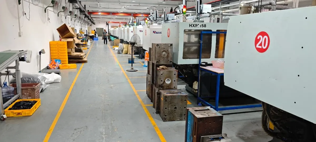
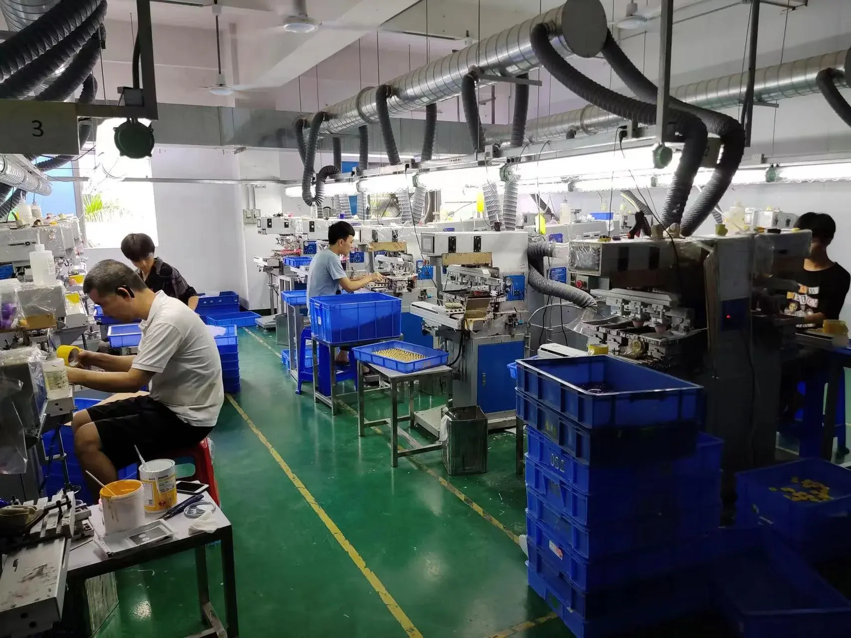
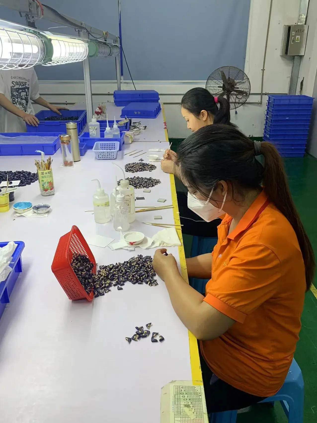
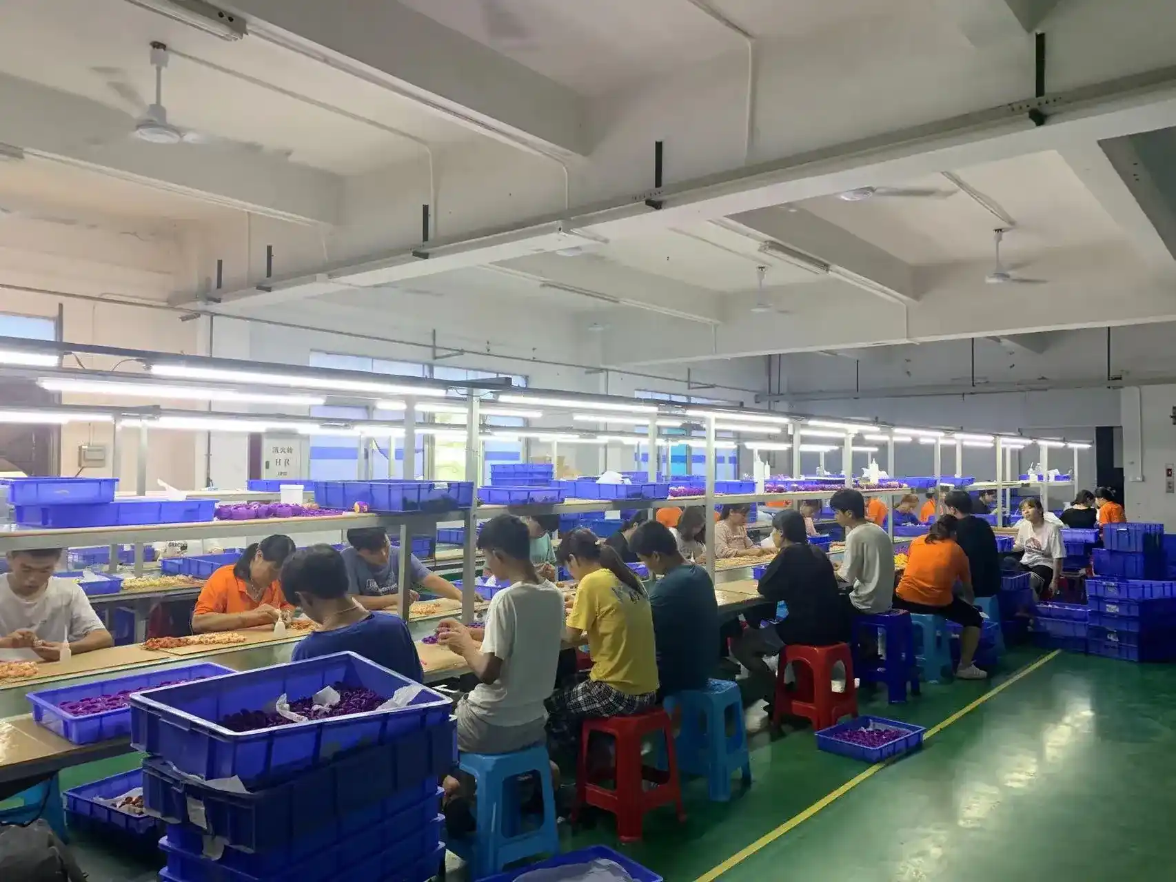
Core development, tooling, molding, decoration, assembly, inspection and final pack-out are managed in-house. Printed boxes, trays, blisters and other packaging components are produced through established partners and coordinated within the approved project plan.
Confirm Tool Ownership and Storage Terms Before Machining
Tooling ownership is not a complete commercial policy by itself. The applicable agreement should identify the physical assets, payment status, custody, use rights and conditions for later maintenance or transfer.
Ownership of a physical tool does not grant rights to character artwork, product designs or other intellectual property. FigCrafts works from buyer-owned, licensed or otherwise authorized designs, and NDA support is available before detailed file exchange.
Ownership & Covered Assets
Identify the production tools, inserts, fixtures or other physical assets included.
Storage, Maintenance and Use
Define custody, identification, permitted use, routine care, wear and repair responsibilities.
Dedicated & Shared Components
Distinguish project-specific items from any common production components used by agreement.
Transfer Conditions
Confirm payment status, packing, destination, transport and related costs if a later transfer is required.
Send Enough Information to Define the Tooling Risk
Early files do not need to be perfect, but a useful evaluation needs more than a product image. Mark what is approved, what is provisional and what still requires engineering review.
Authorized Product Files
3D files, drawings, turnarounds, physical references and the status of each design baseline.
Part and Assembly Plan
Known part breakdown, interfaces, movement, snap or glue logic, insert parts and assembly direction.
Size, Quantity and SKUs
Finished size, estimated production quantity, variants, colors and repeat-order expectations.
Material and Finish Direction
Known material route, visible surfaces, paint, printing, texture and areas that must be protected.
Critical Fit and Quality Points
Dimensions, interfaces, appearance zones, build checks and inspection evidence important to approval.
Packaging, Market and Schedule
Pack-out method, instructions, target market, testing needs, launch timing and approval contacts.
Tooling & Mold Making FAQ
Request a Tooling and Mold-Making Review
Share the files and product details you have now. Our team will review manufacturability, identify missing information and recommend the next step. Initial feedback is typically provided within 1–3 business days once sufficient information is available.