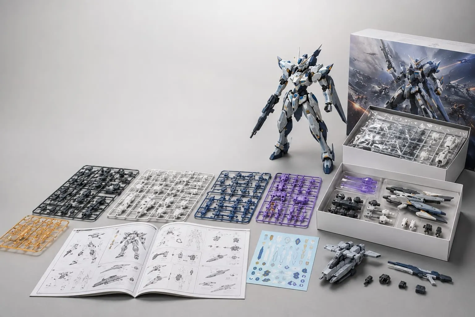
Develop authorized multi-part model kits with one team for part and runner engineering, prototypes, tooling, injection molding, decoration, build checks, instructions and complete retail pack-out.
Why Model Kit Buyers Work With FigCrafts
Precision, accumulated project experience and coordinated delivery matter most when dozens of individual parts must become one complete retail product.
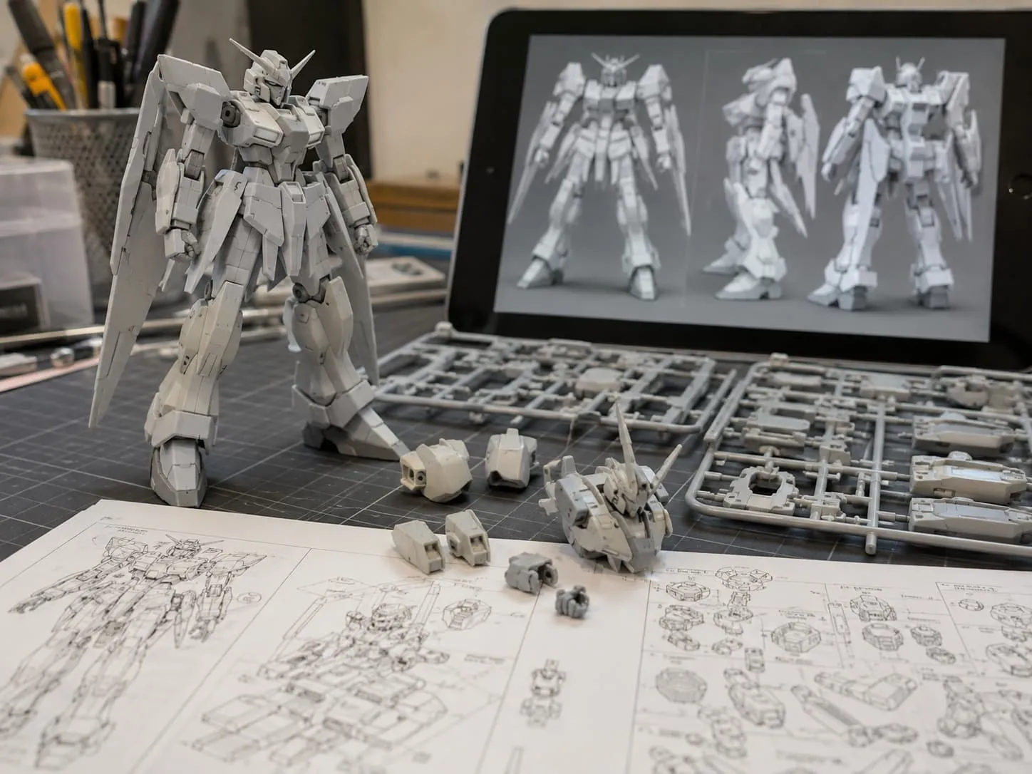 01 / Engineering review
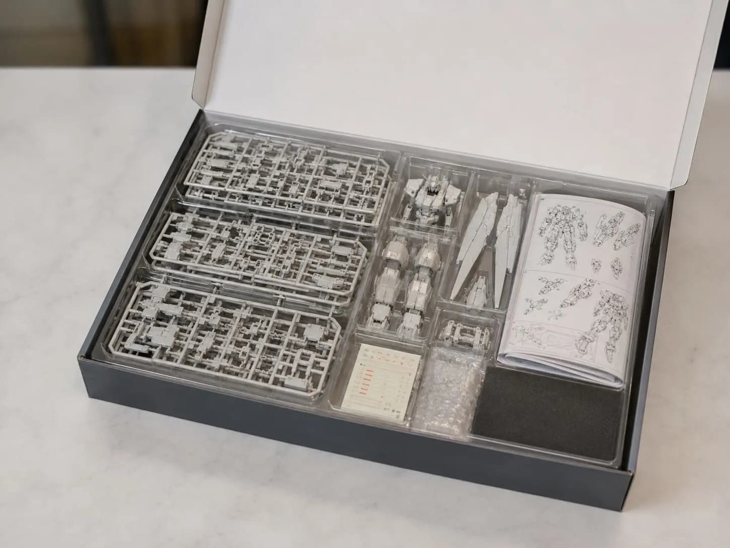 02 / Complete pack-out
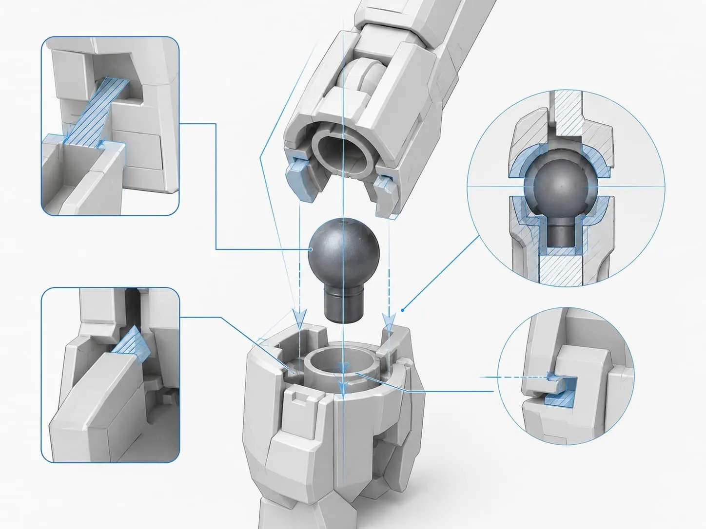 03 / Precision logic
Product precision
Precision Is Built Into the Approval Chain
Part interfaces, assembly direction, visible surfaces, gate locations and the criteria for acceptable fit are reviewed before tooling and translated into sample and production checks.
Project experience
Regular Experience With Japanese Customers
FigCrafts has supported many custom product programs and works regularly with Japanese customers. That experience strengthens drawing discipline, change control, sample sign-off and packaging completeness.
Customer identities and protected project assets are only published when authorization permits.
Coordinated delivery
One Accountable Route From Brief to Pack-Out
Engineering, prototyping, tooling, injection, decoration, inspection and final pack-out are managed as one project plan. Instructions, printed packaging, inserts, testing or logistics can be coordinated with established providers when required.
Is a Plastic Model Kit the Right Product Type?
Choose this route when the customer receives organized molded parts and completes the product through a defined assembly sequence.
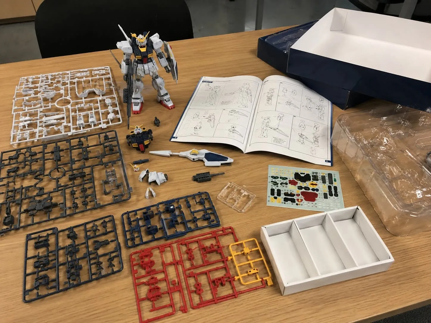 System view / Parts to complete kit
Customer-Assembled Products
Parts stay on runners or sprues, or are organized as loose components, until the customer builds the product.
Multi-Part Character, Mechanical or Display Kits
Complex forms are divided into manufacturable parts with controlled interfaces.
Color-Separated Kit Systems
Molded colors, clear parts, printed details, decals and painted zones are planned together.
Instruction-Led Retail Pack-Out
Runners, loose parts, instructions and packaging must match the correct SKU and build sequence.
The product is incomplete until part numbering, assembly sequence, instructions, protective packing and SKU configuration agree with the approved build.
Engineer Fit, Runners and Visible Surfaces Before Tooling
High precision is not a decorative claim. It is the result of defining what must fit, what may move, what must remain aligned and how those requirements will be approved and inspected.
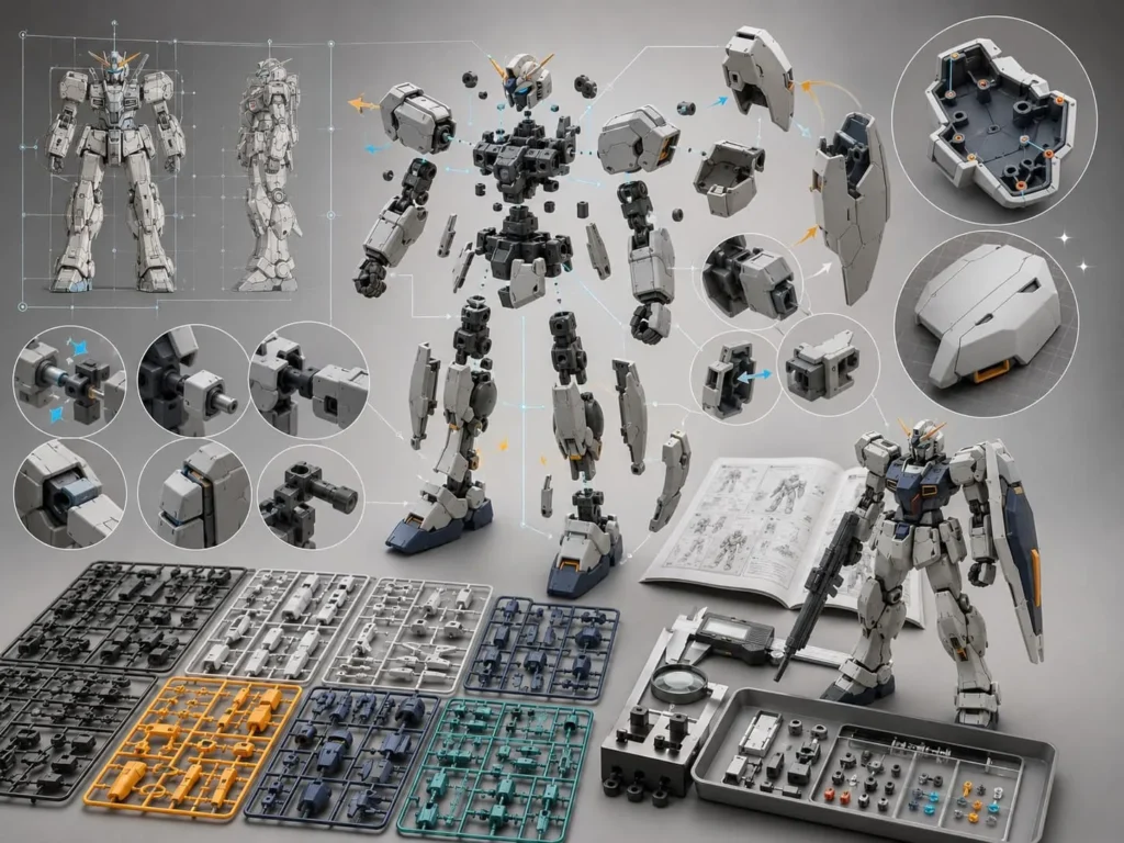
Reference Geometry
Confirm the dimensions and visible relationships the assembled product must preserve.
Part Breakdown
Divide components around molding, release, appearance and the customer build sequence.
Fit and Clearance
Define critical pegs, sockets, keys, tabs, hinges and mating surfaces for the intended assembly method.
Gates & Visible Surfaces
Plan material entry and trimming points around the surfaces customers will see.
Runner and Color Grouping
Organize parts by tooling feasibility, material, molded color and kit-packing needs.
Build and Completeness Checks
Turn the approved build into practical fit, runner, quantity and box-content checks.
What precision means
Different Kit Features Need Different Controls
Select Materials by Part Function and Assembly Behavior
Material recommendations depend on rigidity, surface detail, fit, stress, flexibility, clarity, decoration and applicable testing requirements.
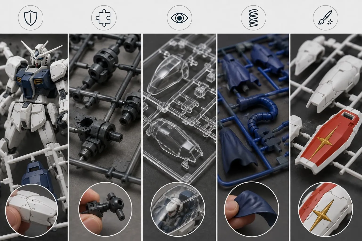 Material behavior / 1–5
Rigidity and Surface
Dimensional stability, molded detail, visible finish, gate location and decoration compatibility.
Fit and Stress
Insertion force, retention, repeated assembly behavior, stress concentration and part geometry.
Appearance and Protection
Clarity, tint, stress, surface marks, separate handling and protection inside the package.
Flexibility and Clearance
Bending behavior, assembly order, collision risk and the effect on adjacent finished surfaces.
Adhesion and Finish
Surface preparation, printing, paint, decal placement, rub areas and approved visual consistency.
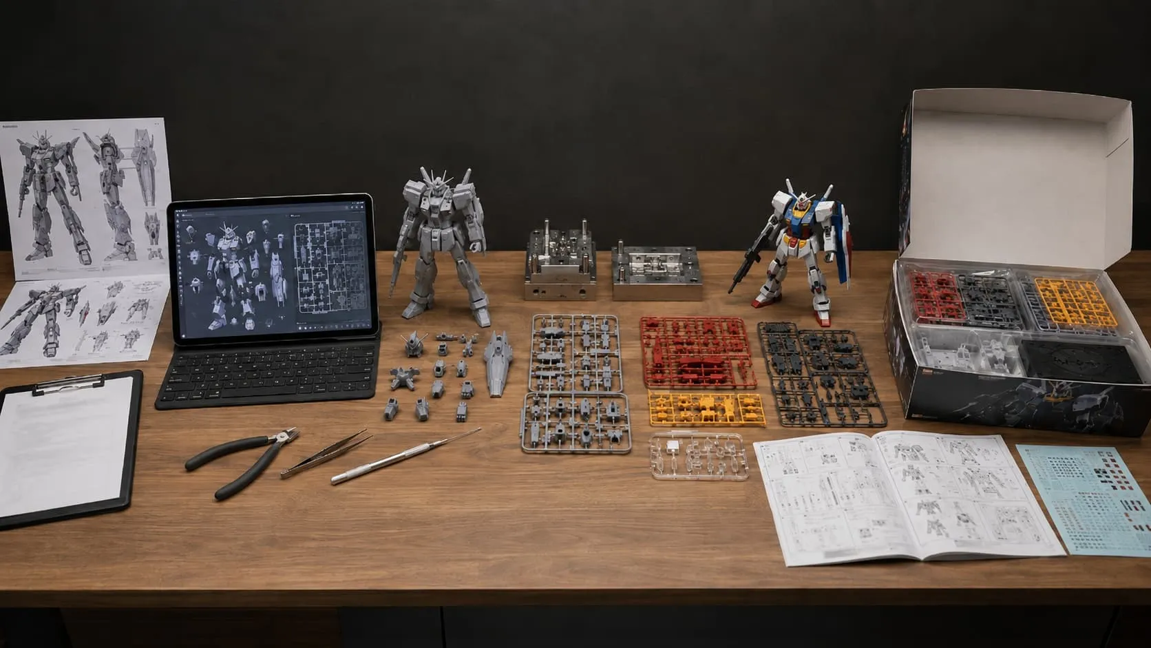
From Authorized Design to a Complete Model Kit
Each stage closes a specific risk before the project advances. The exact route is confirmed after the starting files and finished-product requirements are reviewed.
Project Review
Confirm authorization, assembled size, quantity, market, SKU plan and packaging direction.
Kit Engineering
Develop parts, interfaces, build sequence, runner groups and visible-surface priorities.
Prototype & Build Review
Check form, fit, assembly behavior, handling and appearance.
Tooling & Trial Parts
Build tools, inspect trial parts and complete agreed corrections.
Injection & Decoration
Mold approved parts and apply confirmed printing, paint or other finishes.
Kit Completion & Pack-Out
Verify runners, loose parts, instructions, printed items and SKU configuration before packing.
One Project Team Coordinates Production and Pack-Out
Performed through the FigCrafts manufacturing workflow: product engineering, prototypes, tool design and machining, injection molding, painting, printing, assembly, inspection and final pack-out.
Product Development and Production
Supporting Components and Services
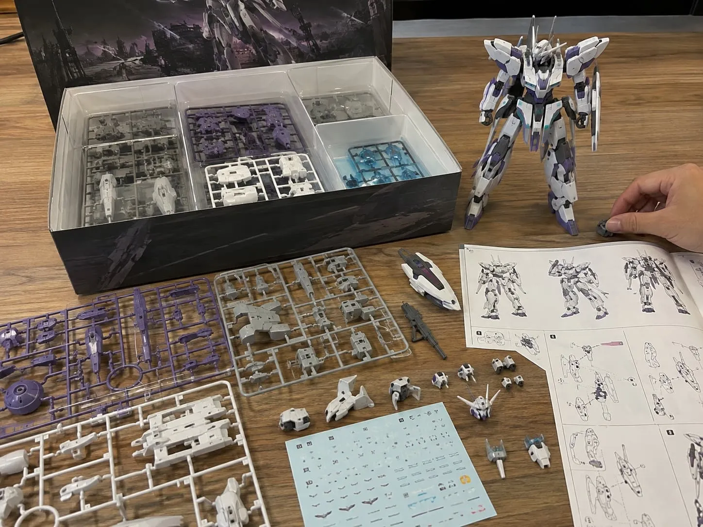
Quality Control Covers the Parts, the Build and the Box
A visually acceptable part can still fail the product if it does not fit, appears on the wrong runner, is missing from the BOM or reaches the wrong SKU pack-out.
 Quality view / Fit + identity + completeness
Tool and Trial-Part Review
Check part formation, visible surfaces, gate condition, critical dimensions and agreed tool corrections.
Assembly and Fit Review
Build the defined sequence and check alignment, insertion, retention, interference and finished appearance.
Runner and Variant Control
Confirm runner identity, molded color, loose parts and the correct SKU assignment.
Final Completeness Check
Verify the bill of materials, instructions, printed items, protective components and carton quantities before release.
FAI, sampling plans, buyer inspection and third-party testing are applied only when defined in the approved quality plan or project agreement.
What Determines a Plastic Model Kit Quote?
Send the information you already have. Missing details can be identified during the initial route review without pretending that a fixed price or schedule applies to every kit.
Assembled Size and Files
Finished dimensions, artwork, 3D data and the current design stage.
Part and Runner Scope
Estimated part count, runner groups, loose parts, clear parts and known assembly structure.
Fit and Assembly Method
Snap-fit, glue assembly, screws, moving features or other critical interfaces.
Color and Decoration
Molded colors, paint, printing, decals, labels and colorway variations.
Quantity and SKUs
Total quantity, quantity per version, launch plan and repeat-order expectation.
Instructions and Packaging
Instruction format, bags, trays, box, labels, cartons, target market and testing direction.
Model Kit, Action Figure or Collectible Figure?
Plastic Model Kit
Choose when the customer assembles an organized set of molded parts.
Custom Action Figure
Choose when joints, pose range and interchangeable accessories define the product.
Review action figure route →PVC & Collectible Figure
Choose when the buyer receives a finished static display piece led by sculpt and decoration.
Review static figure route →Plastic Model Kit Manufacturing FAQ
Request a Plastic Model Kit Project Review
Share the files and product details you have now. Our team will review manufacturability, identify missing information and recommend the next step. Initial feedback is typically provided within 1–3 business days once sufficient information is available.