Tooling for figures and plastic model kits

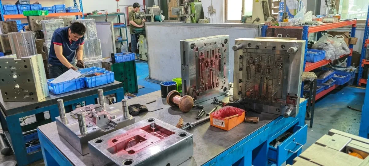
Tooling & Mold Making Built Around Approved Product Decisions

FigCrafts connects product-specific DFM, mold design, machining, controlled trials and production approval for authorized figure and model-kit programs.

The objective is not simply to cut steel. It is to protect the product structure, critical interfaces, visible surfaces and downstream assembly before the tool becomes an irreversible investment.

1786091814109 913ac11d7b68d8
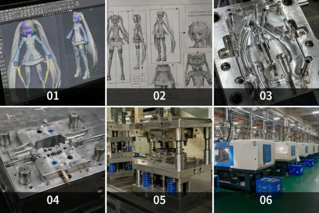
Representative engineering visualization for tooling review
01
Lock the approved product baseline before machining begins.
02
Resolve parting, gate, ejection, fit and appearance as one system.
03
Use trial parts as evidence, not as automatic production approval.
04
Record release status and tooling terms in the project agreement.

Before tooling starts

A Tool Should Reproduce an Approved Product Baseline

When geometry, part relationships or appearance priorities remain open, machining converts uncertainty into cost. The first gate is therefore a product decision, not a machine decision.

01

Geometry and Part Structure

Approved 3D data or physical references should define the part breakdown, interfaces, assembly direction and areas that still require physical validation.

02

Material and Production Route

Material direction, quantity, color variants, decoration and the intended molding route change the tool set, cavity grouping and validation plan.

03

Critical Interfaces and Surfaces

Joints, snaps, pins, sockets, assembly fits, character faces, polished panels and decorated zones need explicit priorities before tool design is released.

04

Approval and Commercial Boundaries

The parties should know who approves machining, trial corrections and production release, and which tooling terms will be recorded in the project agreement.

Readiness gate

Do Not Use the Mold to Discover the Product

Ready   Product geometry and interfaces have an approved baseline.
Ready   Material, quantity and downstream finish route are sufficiently defined.
Ready   Critical fit, appearance and inspection priorities are visible.
Hold   Major part splits, functional relationships or buyer decisions remain open.
Validate the product before tooling

Coupled DFM decisions

Parting, Gating, Ejection and Fit Must Work Together

A decision that helps filling can move evidence onto a visible surface. A split that helps release can create a seam across a decorated face. DFM evaluates these interactions before machining.

Simplified injection mold DFM control diagram A scientific-style diagram showing the fixed and moving mold halves, parting line, runner and gate, ejector direction, cooling paths, a critical dimension and the protected appearance surface. FIXED HALF MOVING HALF Critical Fit Critical dimension Runner and gate Ejection direction Cooling path Parting plane Protected appearance surface

One change can move risk elsewhere.
Engineering explanation only; exact tool architecture follows the approved product, material and production route.
01

Geometry and Release

Draft, undercuts, shutoffs, wall behavior and release direction are reviewed against the intended tool action.

02

Parting and Appearance

Parting evidence, witness-sensitive zones, character faces and polished panels are prioritized before steel is cut.

03

Runner, Gate and Fill

Material path, gate evidence, part balance and runner organization are evaluated with downstream finishing in mind.

04

Venting, Cooling and Ejection

Tool features support fill, thermal control and reliable release without damaging critical faces or interfaces.

05

Dimensions and Assembly

Project-defined critical dimensions, joints, snaps, pins, sockets and mating relationships become review points.

06

Tool, Press and Production Match

The tool structure and operating needs are assessed against the intended material, press route and production sequence.

From DFM to production approval

Six Stages Keep Irreversible Decisions Visible

Every stage converts an open question into an approved baseline, reviewable physical evidence or a controlled release decision.

01

Define

DFM and Tooling Baseline

Confirm parts, interfaces, visible surfaces, material direction, quantity, variants and the checks the tool must support.

Buyer gate: product and tooling scope
02

Plan

Mold Design

Develop the project-specific split, cavity grouping, runner and gate direction, ejection, cooling and operating concept.

Buyer gate: decisions before machining
03

Build

Machining and Tool Assembly

Machine and assemble the approved tool structure while recording technical changes against the released baseline.

Gate: tool prepared for controlled trial
04

Test

Controlled Trial

Produce reviewable parts and record observed forming, surface, dimension, fit, assembly and downstream behavior.

Buyer gate: evidence and finding classification
05

Correct

Correction and Verification

Separate tool correction, buyer product change and process optimization, then verify the agreed action.

Buyer gate: correction status
06

Release

Production Approval

Confirm the agreed criteria, approved reference and outstanding conditions before routine production begins.
Buyer gate: documented production release

Trial evidence, not automatic release

A First Trial Shows What the Machined Tool Actually Produces

T1 commonly describes a first tool trial and T2 may describe a later trial after corrections. Naming and trial count vary; agreed evidence and release criteria control the decision.

Trial evidence

What the Parts Can Reveal

Forming, fill or visible process effects
Parting, gate and ejection evidence
Project-defined dimensions and interfaces
Fit, movement, stability and assembly behavior
Impact on painting, printing and final pack-out

Classify Correct Verify

Production release

What Must Be Agreed

Accepted product and appearance reference
Critical inspection points and method
Closed corrections and open conditions
Assembly and downstream process status
Authority to enter routine production
01 / Tool Correction

Return to the Agreed Baseline

A trial result that does not meet an approved tool or part requirement is documented and reviewed as a tool correction.

02 / Buyer Product Change

Change the Approved Baseline

New geometry, material, fit or appearance requirements are assessed for tool impact, cost and schedule before work proceeds.

03 / Process Optimization

Improve the Production Window

Operating adjustments are separated from product redesign and permanent tool changes so responsibility stays visible.

One accountable production chain

The Tool Is Connected to Injection, Finish, Assembly and Pack-Out

Tool decisions are reviewed against the processes that follow. This protects visible surfaces, assembly access, decoration boundaries, part handling and final completeness instead of treating the mold as an isolated purchase.
Engineering

Tooling

Injection

Decoration

Assembly

Pack-Out

Quality Release
1786091814159 8faf7e18a0b14
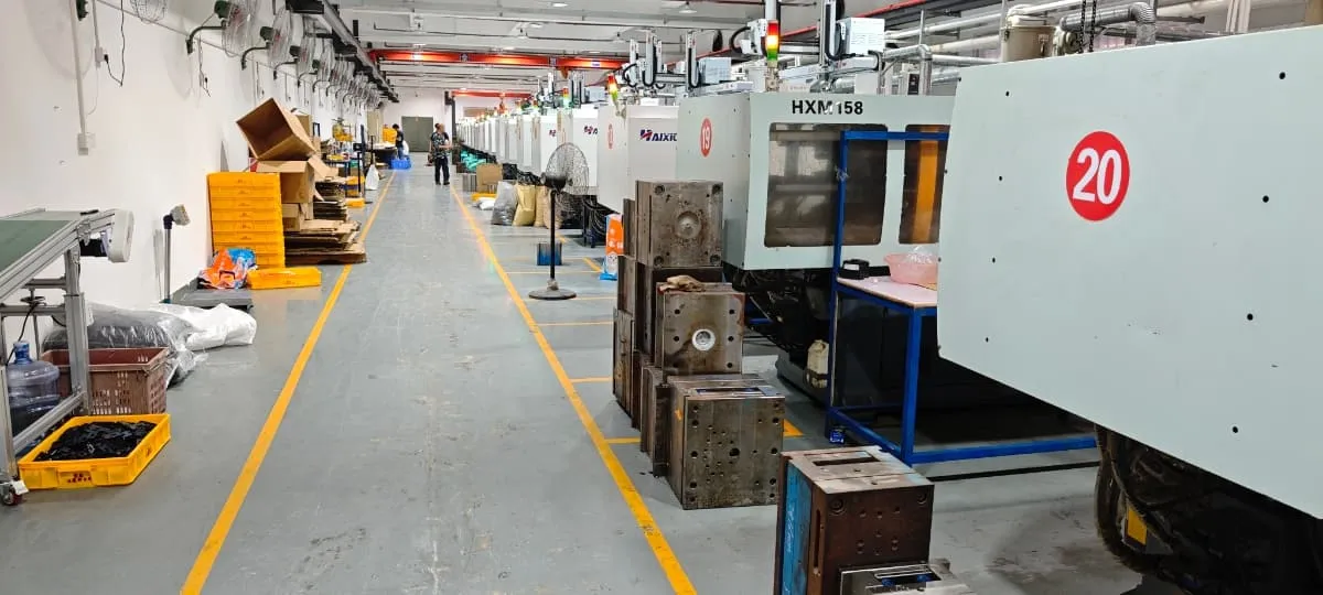
Injection production
Company production photography from the FigCrafts source profile.
1786091814131 6a5703ee832b4
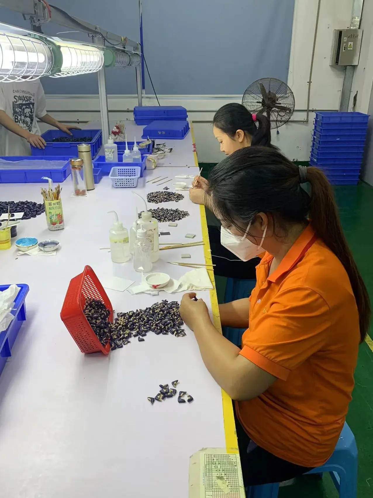
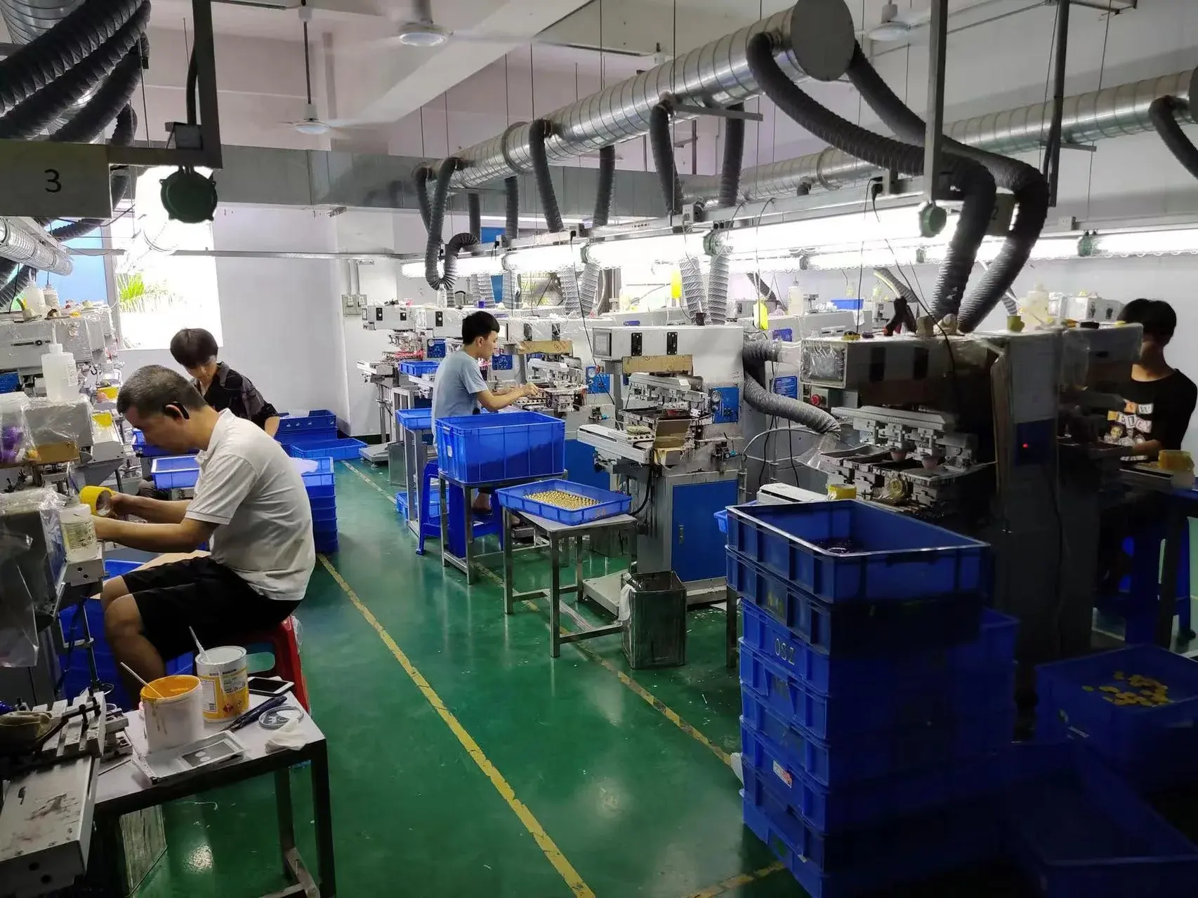
Pad printing
Company production photography.
1786091814146 e4de7ed1bd5008
Hand finishing
Company production photography.
1786091814164 75565016224fd8
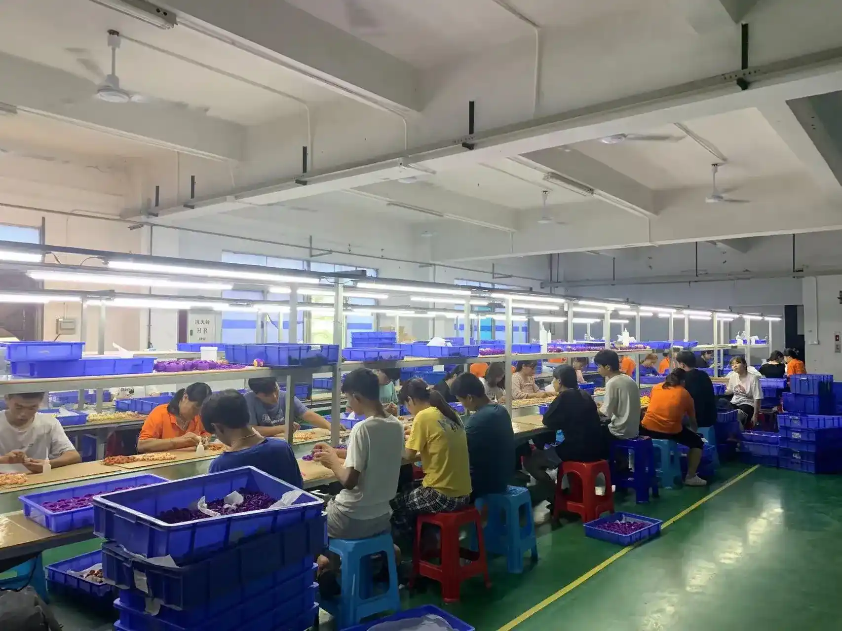
Assembly
Company production photography.
Complete delivery with visible boundaries.

Core development, tooling, molding, decoration, assembly, inspection and final pack-out are managed in-house. Printed boxes, trays, blisters and other packaging components are produced through established partners and coordinated within the approved project plan.

Review assembly and packaging coordination →

Tooling terms and lifecycle

Physical Tooling Controls Belong in the Project Agreement

Tooling ownership is not a complete commercial policy by itself. The applicable agreement should identify the physical assets, payment status, custody, use rights and conditions for later maintenance or transfer.

Ownership of a physical tool does not grant rights to character artwork, product designs or other intellectual property. FigCrafts works from buyer-owned, licensed or otherwise authorized designs, and NDA support is available before detailed file exchange.

Discuss Tooling Terms
01

Ownership and Covered Assets

Identify which production tools, inserts, common mold bases or other physical assets are included.

02

Storage, Maintenance and Use

Confirm custody, permitted use, identification, preventive work, wear, repair and later modification responsibilities.

03

Dedicated Fixtures and Shared Components

Separate dedicated jigs, fixtures and inserts from any shared or common production components used by agreement.

04

Payment, Transfer and Transport

Define how unsettled charges, release preparation, packing, destination, transport conditions and related costs affect any transfer.

Inputs for an effective evaluation

Send Enough Information to Define the Tooling Risk

Early files do not need to be perfect, but a useful evaluation needs more than a product image. Mark what is approved, what is provisional and what still requires engineering review.

01

Authorized Product Files

3D files, drawings, turnarounds, physical references and the status of each design baseline.

02

Part and Assembly Plan

Known part breakdown, interfaces, movement, snap or glue logic, insert parts and assembly direction.

03

Size, Quantity and SKUs

Finished size, estimated production quantity, variants, colors and repeat-order expectations.

04

Material and Finish Direction

Known material route, visible surfaces, paint, printing, texture and areas that must be protected.

05

Critical Fit and Quality Points

Dimensions, interfaces, appearance zones, build checks and inspection evidence important to approval.

06

Packaging, Market and Schedule

Pack-out method, instructions, target market, testing needs, launch timing and approval contacts.

Start with the baseline you have

Request a Tooling and Mold-Making Review

Share the available files, product route, estimated quantity and open engineering decisions. FigCrafts can then assess what should be resolved before tooling is released.

Product and part baseline
Critical fit and appearance priorities
Tooling, production and pack-out scope

Shared Inquiry Form

Add a native Elementor Form widget here after import.

Tooling buyer FAQ

Questions to Resolve Before the Tool Becomes an Asset

The answers below separate confirmed capability from the project-specific decisions that still require engineering and commercial review.

What must be approved before production tooling begins? The product geometry, part structure, material direction, critical surfaces and interfaces, estimated quantity, variant plan and approval baseline should be sufficiently defined. A prototype or physical build review may come first when important product decisions remain open.

Can FigCrafts support tooling for both figures and plastic model kits? Yes. The tooling route is adapted to the product. Model kits emphasize part and color grouping, runners, gates and assembly fit; action figures add joints and mixed interfaces; static figures emphasize part split, appearance, joining and stability.

How are parting lines, gates, ejection and appearance controlled? They are reviewed together during product-specific DFM and mold design. The agreed approach considers release direction, material flow, gate evidence, visible surfaces, ejection risk, critical dimensions, assembly and downstream painting or printing.

Do T1 or T2 trial parts automatically approve production? No. T1 commonly describes a first tool trial and T2 may describe a later trial after corrections, but naming and trial count vary. Production approval depends on the agreed evidence, closed corrections, approved reference and release criteria.

What documents or reports are included with a tooling project? The project-specific approval package may include the product and tooling baseline, DFM decisions, trial parts, dimensional or fit evidence, finding records, correction status and a release record. The exact format and depth are confirmed in the agreed inspection and project plan.

How are tooling ownership, storage and transfer handled? Ownership, covered physical assets, storage, maintenance, permitted use, transfer, common mold bases, dedicated fixtures, unsettled charges, packing and transport conditions are confirmed in the project agreement. Physical tool ownership is separate from product-design and character IP rights.

Can confidential programs use an NDA, and does FigCrafts have experience with Japanese customers? NDA support is available before detailed file exchange. FigCrafts has confirmed experience supporting Japanese customer programs, particularly detail-driven model products. Customer identities, protected designs and project images are published only when the necessary authorization is available.

How does tooling connect to decoration, assembly and packaging? Tool decisions are reviewed against injection, painting, printing, assembly, inspection and final pack-out requirements. Printed boxes, trays, blisters and other packaging components can be partner-produced and coordinated within the complete delivery plan.

Approve the decisions before the investment

Send the Product Baseline for a Tooling Review

Share authorized files, part and assembly information, quantity, materials, critical fit, finish, packaging and target schedule. FigCrafts will review the route before tooling scope is confirmed.

Send Your Inquiry

Share project details for an initial manufacturing review.

*For confidential files, request an NDA before sharing sensitive project data.

滚动至顶部

Send Your Inquiry

Share project details for an initial manufacturing review.

*For confidential files, request an NDA before sharing sensitive project data.