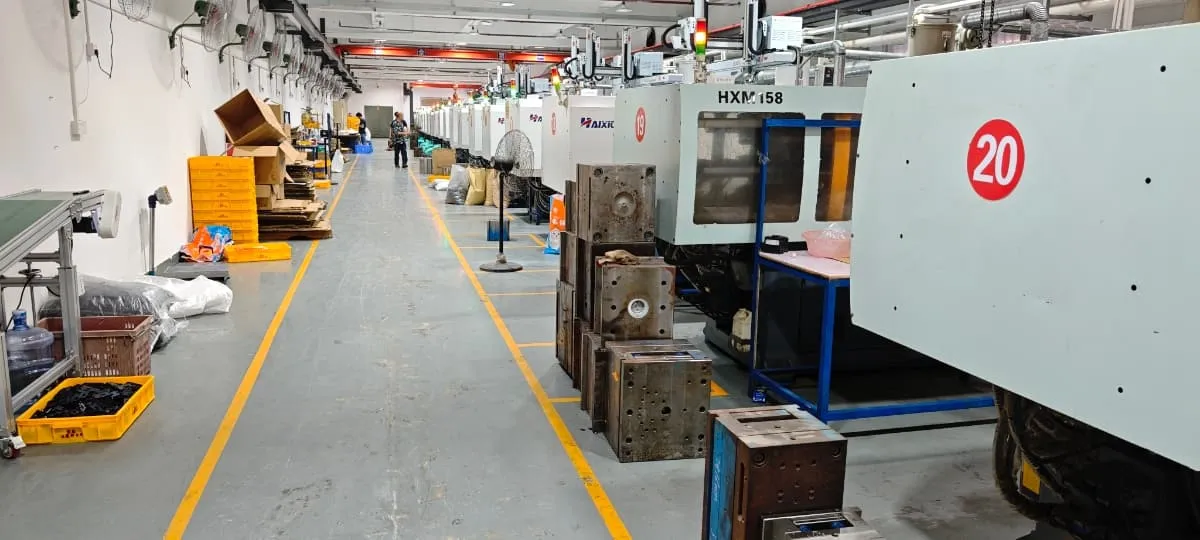
Produce controlled plastic parts for custom model kits, action figures and collectible products on 45 servo injection molding machines from 80T to 850T, including two rotary two-color machines.
A clear boundary from tooling
What Is Needed Before Production Molding Starts?
DFM, parting, gate and ejection strategy, tool machining, tool trials and tool-asset terms belong to the tooling stage. Injection production uses the released result as a controlled input.
Review Tooling & Mold Making →The tool identity, trial status and any remaining operating conditions are clear.
Part or runner organization and critical interfaces refer to the current approved revision.
Resin and molded-color requirements are confirmed for the production review.
Quantity, SKUs, critical checks, downstream work and approval responsibility are defined.
Match the Tool and Material to the Right Machine
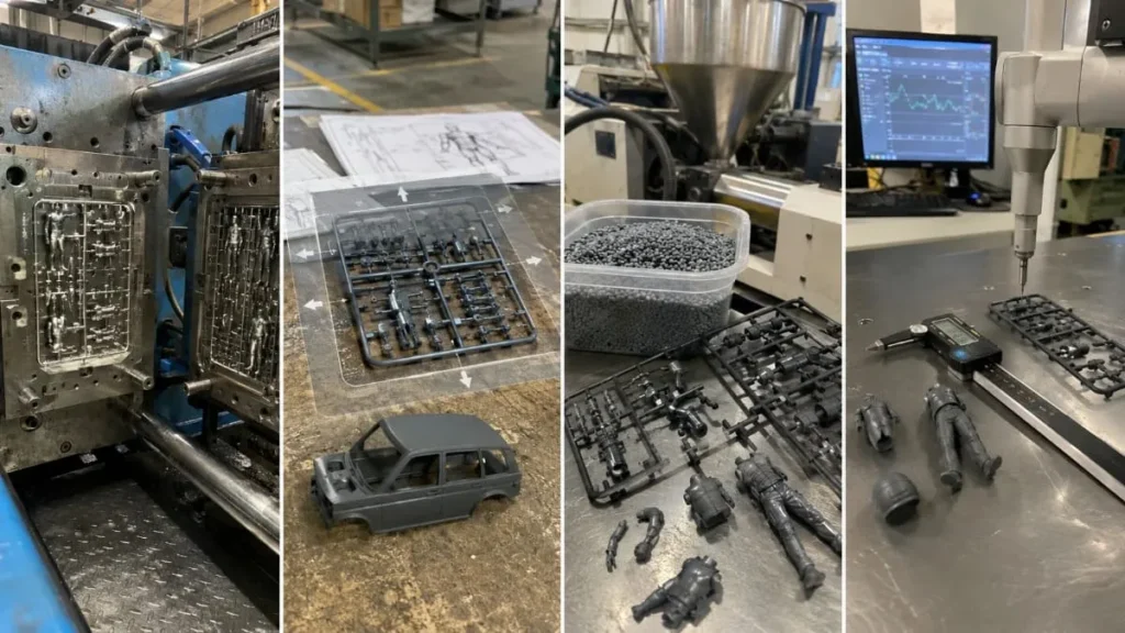
The 80T–850T range describes the available equipment; final feasibility depends on the complete molding setup.
Tool Size & Operation
Mounting, opening, slides, inserts, ejection and handling must fit the selected press.
Projected Area & Clamp Requirement
Part geometry, cavities and material behavior influence the required clamping force.
Material & Shot Size
The resin, runner system and total shot must fit the machine and production process.
Stable Production Window
The selected combination must support repeatable forming and the agreed inspection plan.
Production Checks Follow the Finished Product
Plastic Model Kits
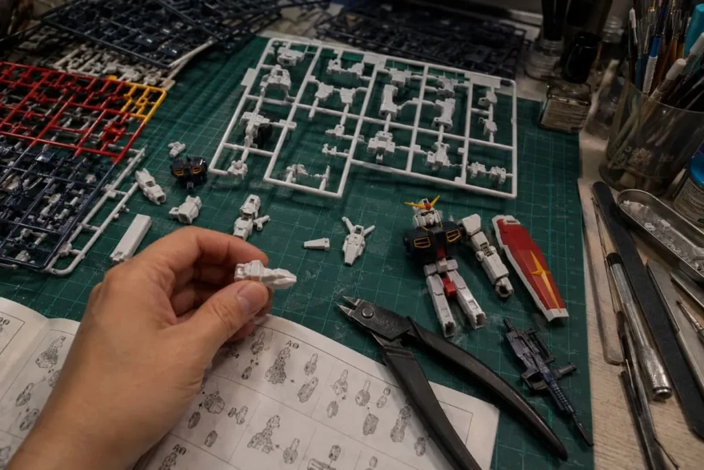
Check complete parts, runner condition, part IDs, color groups, visible gate areas, deformation and selected build fit.
Review Plastic Model Kits →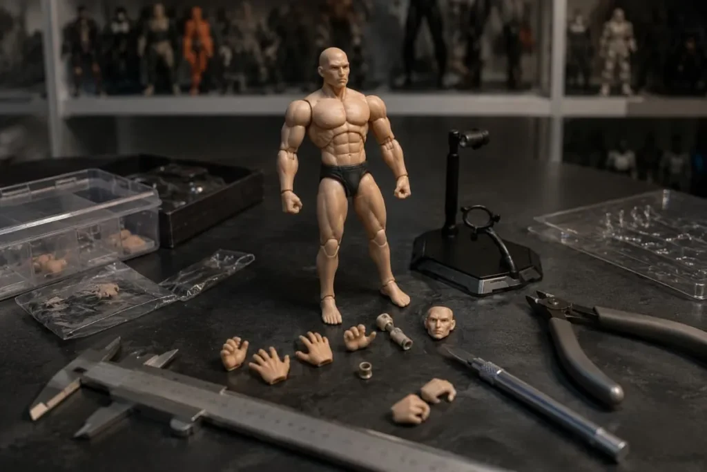
Action Figures
Check joints, pins, sockets, bases and accessories against the required fit, movement, stability and interchangeability.
Review Action Figures →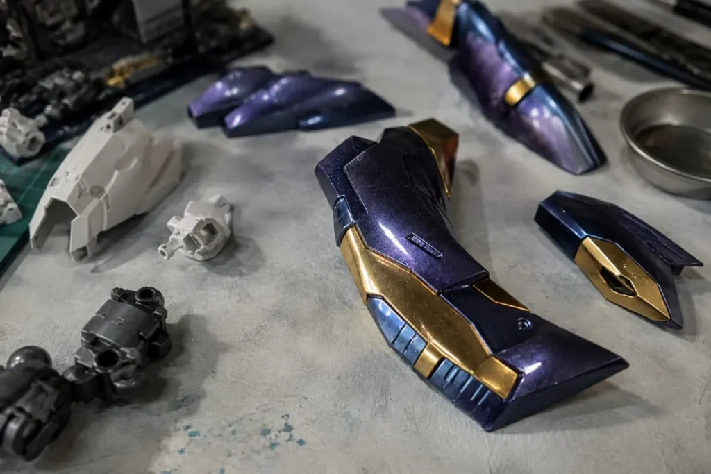
Decorated Figure Parts
Check filling, flash, sink, flow or handling marks on surfaces that remain visible or receive paint and print.
Review PVC Figures →How an Injection Production Run Is Controlled
The exact records and sampling plan are agreed per project. The gates keep the starting condition, production findings, reaction and downstream decision visible.
Confirm Inputs
Verify the released tool, material, molded color, quantity, SKUs and critical product requirements.
Review First-Off Parts
Check the current production setup against the agreed first-article characteristics.
Monitor Routine Production
Apply the agreed sampling, identification, handling and reaction plan during the run.
Release Molded Parts
Confirm accepted condition, count and identification before parts move to decoration or assembly.
Product-specific control matrix
Inspect the Characteristics That Affect the Finished Product
The control plan identifies what is reviewed, how evidence is obtained, when sampling occurs and what reaction follows a result outside the agreed condition.
Complete parts, runner or gate condition, part IDs, color grouping, visible nub areas and frame handling.
The end user must receive every build part in the intended kit organization.
Project-defined mating features, deformation, snap or assembly behavior and selected build checks.
A visually acceptable part can still fail when it meets another component.
Joints, pins, sockets, bases, accessories and agreed critical dimensions or fit conditions.
Variation can affect movement, stability, assembly and interchangeability.
Short fill, flash, sink or flow evidence, visible marks and handling condition.
Surface findings can remain visible or interfere with painting and printing.
Approved material identity, formed color direction and project-specific evidence.
Material or color changes can affect function, appearance and downstream processing.
Part count, cavity or variant identification, lot status and downstream handoff.
Released molded parts must arrive at the next stage complete and identifiable.
What a Production First Article Confirms
A production first article checks the released tool, approved material or color and current setup before routine production. It confirms the agreed starting condition; it does not automatically approve the full lot.
If a check is outside the agreed requirement, affected parts are identified and held, the cause and correction are reviewed, the required check is repeated and parts move forward only after the agreed approval.
The approved inputs and responsibility are visible before setup.
The current setup is checked against agreed characteristics.
Production continues under the agreed control and reaction plan.
When a result is outside the agreed condition
Detection Must Lead to a Controlled Decision
The affected material is not treated as released merely because production has already started.
Protect affected parts, identity and status.
Review the finding and apply the agreed correction route.
Repeat the required check after correction.
Transfer only through the agreed approval authority.
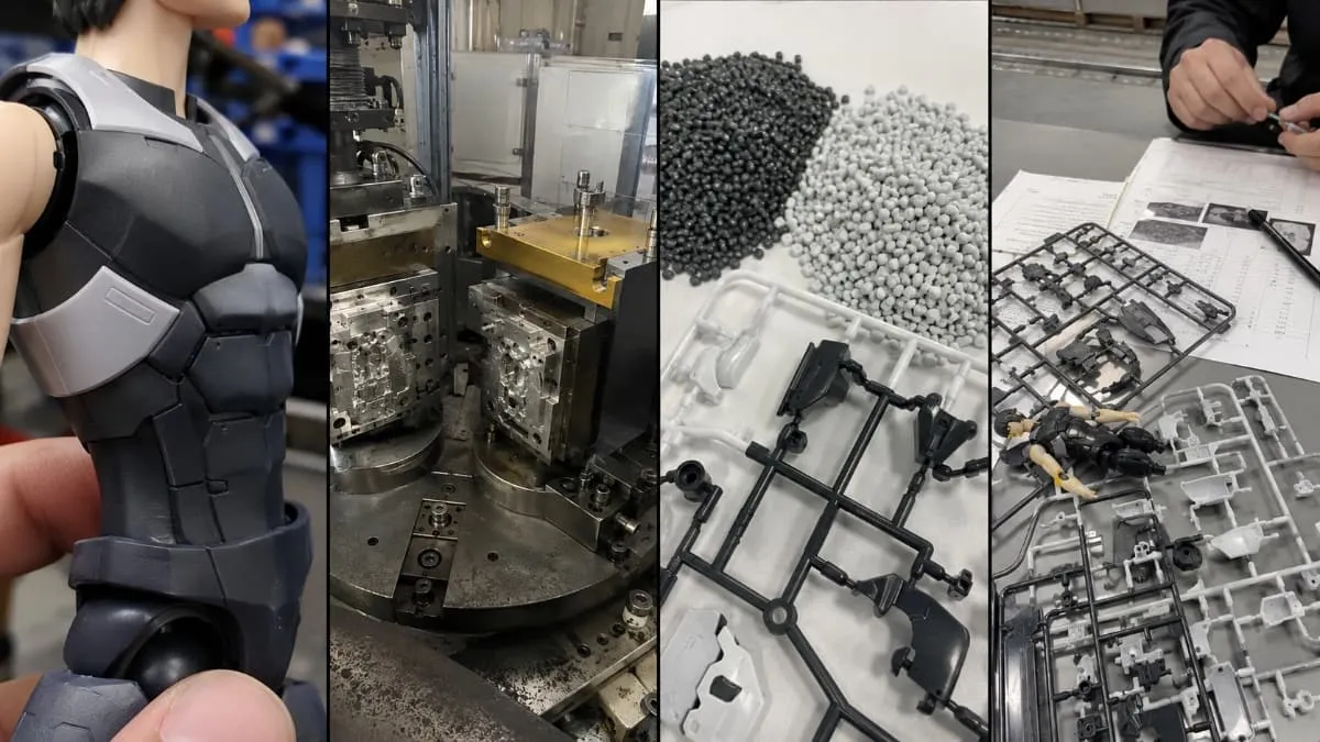
Confirmed rotary two-color equipment
Two-Color Injection Molding
FigCrafts has two rotary two-color injection molding machines. Feasibility depends on the visible or functional interface, tool sequence, material compatibility or mechanical retention, required appearance, volume and product testing needs.
Product Interface
Define the visible or functional boundary and the reason to combine two formed inputs.
Tool Sequence
Confirm reliable positioning and the relationship between the first and second shot.
Material Behavior
Review compatibility, bonding or mechanical retention and required performance.
Commercial Fit
Compare tooling complexity, volume and downstream impact before selection.
Prototype Quantity and Injection-Production MOQ
A validation sample and an injection production order solve different problems. The chosen route should match what the buyer needs to prove and whether production tooling is commercially justified.
From One Unit by a Suitable Non-Production Route
3D printing, vacuum casting or another suitable process can support form, fit, presentation or approval needs without presenting the result as one-unit injection production.
Review prototype routes →Typical MOQ: 500–1,000 Units
The actual requirement depends on product structure, tooling, material, colors or SKUs, finishing and packaging. Whether quantity can be combined across variants is confirmed in the quotation.
Prepare the production RFQ →A defined downstream handoff
Release Molded Parts for the Next Manufacturing Stage
Injection molding does not replace decoration, assembly or finished-product quality control. It transfers identifiable, accepted molded parts into those downstream responsibilities.
What to Send for an Injection Molding Review
Mark what is approved, what is provisional and what still requires production or commercial review.
Released Tool Status
Tool identity, location, approved status and any operating conditions or unresolved production restrictions.
Material and Formed Color
Approved resin grade, performance direction, color reference or constraints when available.
Quantity, SKUs and Variants
Total quantity, color or SKU split, required sets, reorder assumptions and target schedule.
CTQs and Acceptance
Critical dimensions, interfaces, visible surfaces, build or assembly checks and defect boundaries.
Evidence and Approval
Required first-article, dimensional, color, fit, material or sampling evidence and approval responsibility.
Downstream Requirements
Decoration, handling, assembly, packaging, market or testing needs that affect molded-part release.
Injection molding buyer FAQ
Injection Molding FAQ
Start from a released production program
Request an Injection Molding Review
Share the files and product details you have now. Our team will review manufacturability, identify missing information and recommend the next step. Initial feedback is typically provided within 1–3 business days once sufficient information is available.